
In most circuits where operational amplifiers are used, a positive voltage and a negative supply voltage are required. These voltages are obtained from a symmetrical source or source of two voltages, one being positive and one negative.
In figure 1 we have a power supply circuit of 6 to 15 V, depending only on the transformer and the regulator integrated circuit used.
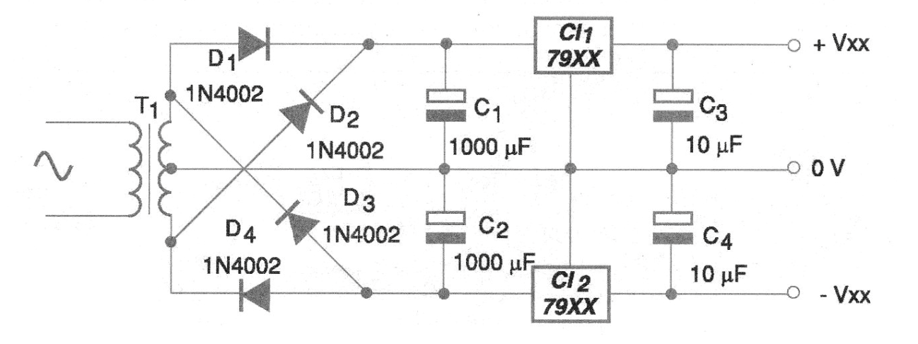
In fact, what we have is a source that combines the two previous circuits, in a single having a unique land reference. The printed circuit board for mounting this source is shown in figure 2.
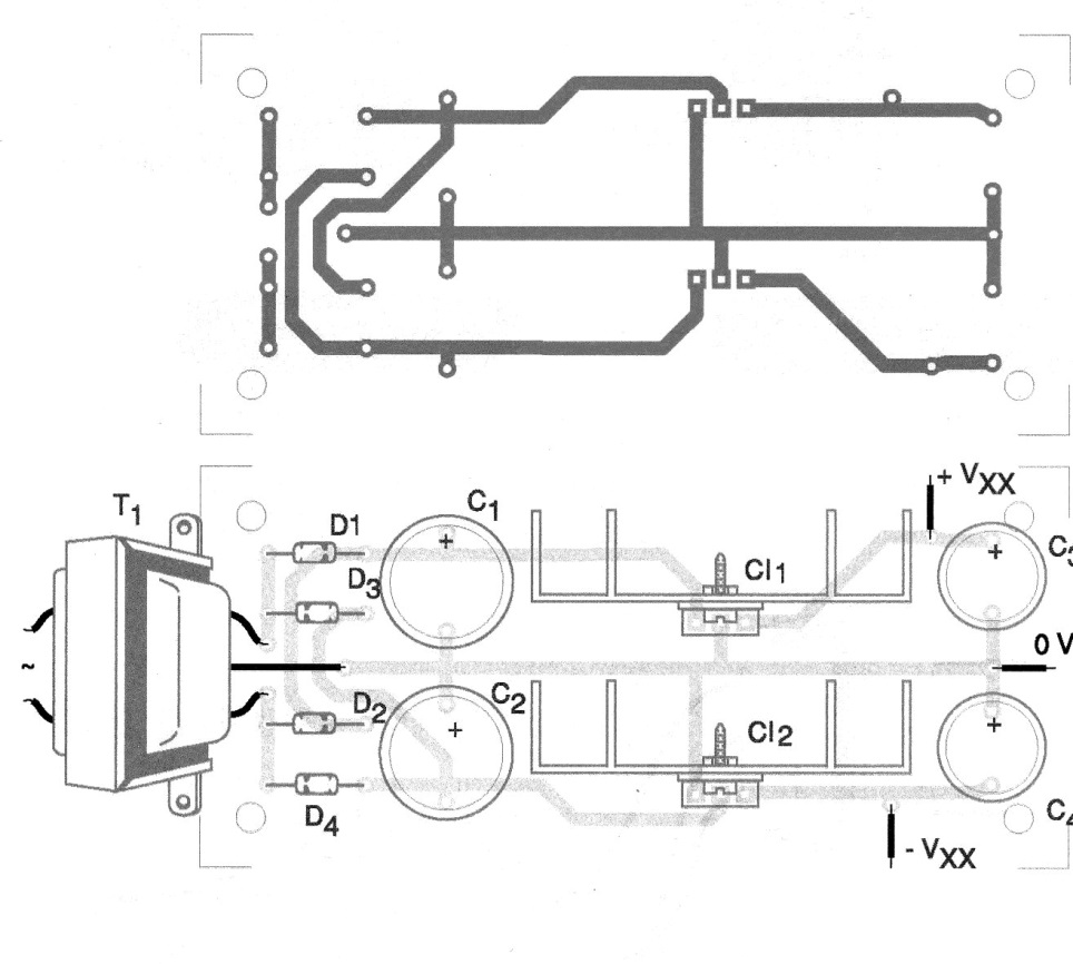
The transformer must have a secondary voltage with approximately 2 volts more than the desired voltage at the symmetrical source output. For example, for a 12 + 12 V source, use a 15 + 15 V transformer.
The maximum current from this source is 1 A and this should be the maximum current of the transformer secondary used. Voltage regulator integrated circuits should be mounted on heat radiators.
Material list
CI-1 - 78xx - integrated circuit voltage regulator
CI-2 - 79xx - integrated circuit voltage regulator
D1, D2, D3, D4 - 1N4002 - rectifier diodes
C1, C2-1000 uF - electrolytic capacitors
C3, C4-10 uF - electrolytic capacitors
T1 - Transformer - see text
F1 - 500 mA - fuse
Several:
Printed circuit board, heat radiators for integrated circuits, power cable, socket for fuse, wires, solder,


