
Increase the sound intensity of your piezoelectric buzzer with the circuit we present. This audio oscillator powers a transformer that raises the voltage to the buzzer to a very high value, thus obtaining high power sound.
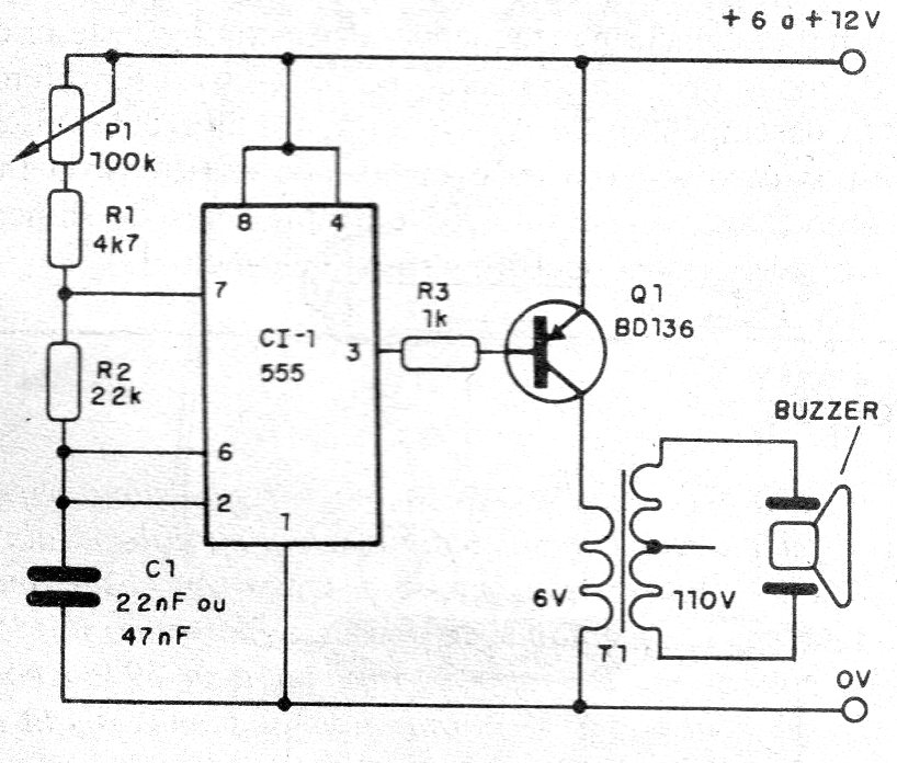
This circuit consists of a simple adjustable audio oscillator with integrated circuit 555, which feeds a power stage to drive a common ceramic piezoelectric transducer.
With the use of a small transformer, the voltage applied to the buzzer is high and with this we have a much higher sound intensity.
Care should be taken only to verify that the buzzer used can be used with high voltages, although this may occur in most cases.
The voltage rise is achieved through a common secondary transformer of 6 to 12 V and any current between 200 and 500 mA.
The primary winding can also be 110 V or 220 V, without problems.
In figure 1 we have the complete diagram of the powerful buzzer.
As this project can be realized with didactic or experimental purposes, we show its assembly based on a solderless board, as shown in figure 2.
23Figure 2 - Assembly in solderless board
On assembly, note the position of the integrated circuit and the polarity of the power supply.
The position of the transistor must also be observed and in this assembly it will not be necessary to use a heatsink.
Material list
CI-1 - 555 - integrated circuit
Q1 - BD136 or TIP32 - PNP power transistor
P1 - 100k ohms - potentiometer
R1 - 4k7 x 1/8 W - resistor - yellow, violet, red
R2 - 22k ohms x 1/8 W - resistor - red, red, orange
R3 - 1k ohms x 1/8 W - resistor - brown, black, red
T1 - transformer - see text
C1 - 22 nF to 47 nF - ceramic or polyester capacitor
BZ - Piezoelectric Buzzer
Several:
Solderless board, wires, source or batteries of 6 to 12 V, etc.


