
Here is a power supply for your small-battery, calculator, or other low-power device that uses standard batteries and whose required current is not more than 100 mA. This power supply does not use a transformer and can be installed on a very small card.
A transformerless source can not provide high currents nor the safety of a source using this component that isolates the network thus avoiding shocks. However, in certain applications the economy may be important and this occurs with small radios and calculators.
The source we describe provides 3 to 12 V output (2 to 8 small cells) with currents up to 100 mA. We can mount it on an easy-to-use printed circuit board and install it in a small plastic soapbox or smaller size.
ASSEMBLY
In figure 1 we have the complete diagram where we observe that the voltage drop plus the current limitation are obtained from a polyester capacitor and a zener diode.
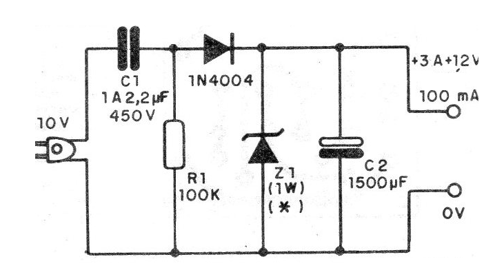
The basic circuit is for the 110 V network but can operate on the 220 V network if C1 is reduced to 1 uF or 470 nF. In figure 2 we have the printed circuit board for this assembly.
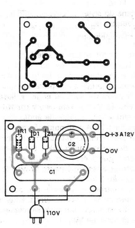
The capacitor C1 must be polyester with a working voltage of 450 V at least if its network is 110 V and 600 V if its network is 220 V. As the sizes of these components vary according to the voltage and the manufacturer it will be convenient to determine the separation of the holes for their bonding on the board after having it in hand.
The zener diode is according to the desired voltage, that is, from 3 to 12 V and its dissipation must be 1 W. The capacitor C2 has a working voltage at least 50% higher than the zener voltage. If the zener is 9 V, for example, we recommend a capacitor for 15 V.
The output is obtained by two wires and we remember that the common 0 V is directly connected to the mains, so there is danger of shock if it is touched. (This is the disadvantage of a transformerless power supply.) In figure 3 we show how to adapt to the radio or calculator using a "closed circuit" type jack.
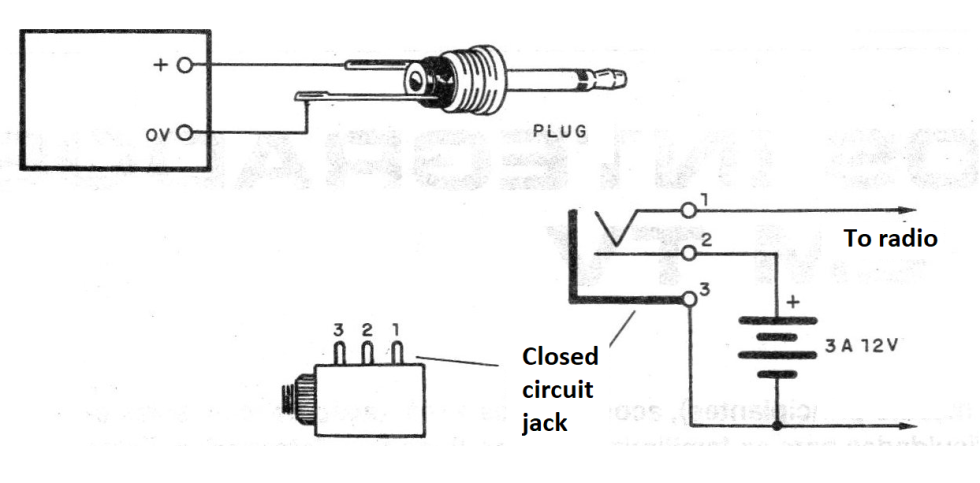
Note that it is very important to observe the polarity of these connections, because if there is any inversion, not only does the powered device not work, but it can even burn components.
MATERIAL LIST
D1 - 1N4004 or equivalent - silicon diode
Z1 - 1W zener diode
C1 to 1 to 2.2 uF - polyester capacitor to 450 V or more
R1 - 100k x 1/8 W - resistor (brown, black, yellow)
C2 - 1500 uF or more - electrolytic capacitor
Miscellaneous: printed circuit board, power cord, wires, jacks, plug, etc.


