
This timer can provide one-hour interval control. At the end of the programmed time, you switch on a light bulb or, if you prefer, switch on a relay. The circuit is powered by 4 or 6 common and fairly compact batteries, which allows it to be installed in a small plastic housing.
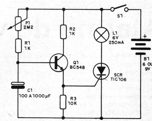
In this circuit the capacitor C1 slowly charges through P1 and R1 until sufficient voltage is reached to polarize the transistor Q1 in the direction of firing the SCR. With the use of a potentiometer of 2M2 and a capacitor of 1 000 uF we have the longest possible time, of the order of 1 hour, depending on the possible existence of leaks in the capacitor.
In figure 1 we have the timer diagram.
In Figure 2 we have the arrangement of the components on a terminal strip.
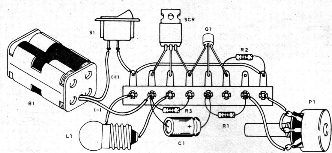
The SCR can be TICIIO6 or equivalent for 30 V or more, and does not need to be fitted with a heat radiator, unless the lamp supplied is more than 500 mA. Under these conditions, we must use battery instead of batteries in the power supply. The L1 lamp is a 6-volt flashlight with a current of up to 250 mA.
The transistor can be any NPN of general use and the resistors are all 1/8 or ¼ W with any tolerance. The capacitor is 1000 uF with a working voltage of 6 V or more.
TEST AND USE
Just turn on the unit. Depending on the time set in P1, the SCR should trip after the set interval by turning on the lamp. To reset the unit, switch the S1 switch off and on again.
As the capacitor C1 retains its charge for some time, for a new cycle of operation it is convenient to discharge it. We can do this with an additional pressure switch connected between its terminals.
If you want to make a time scale for the potentiometer you can use as base a watch or common stopwatch. Another interesting possibility is to use a buzzer at the exit, rather than the lamp.
If the trip is immediately after the S1 connection, check the status of the SCR and the transistor itself. The circuit can also be powered with 12 volt battery or source voltage as long as the lamp is replaced by one that supports this voltage.
MATERIAL LIST
SCR - TIC106 or equivalent - silicon controlled diode
Q1 - BC548 or equivalent - general purpose NPN transistor
S1 - single switch
B1 - 4 or 6 small or medium stacks
P1 - 2M2 - potentiometer
R1, R2 - 1k - resistors (brown, black, red)
R3 - 10 k - resistors (brown, black, orange)
C1 - 100 to 1000 uF x 6 V - electrolytic capacitor
L1 - 6V x 25mm lamp
Miscellaneous: terminal bridge, battery holder, knob for potentiometer, mounting box, wires, soldering etc.


