
We describe a simple timer or timer that can turn on or off an electrical or electronic device after up to 10 minutes. With the use of good quality capacitors and a potentiometer of 1M we can arrive at intervals of up to 1 hour.
The circuit is quite simple to use, operate and assemble. The controlled device has its power passing through the timer relay. When you press the timer switch it is activated by turning the controlled appliance on or off.
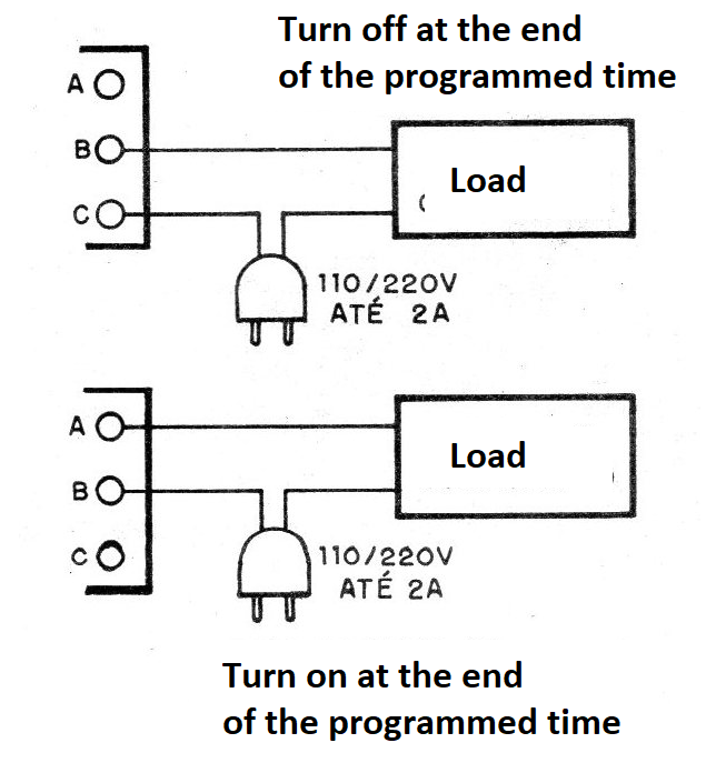
After the set time has elapsed, the timer automatically shuts off its own power by deactivating the relay. With relay deactivation depending on the function used (NA or NF), the external controlled device will be switched on or off depending on the initial situation.
To reactivate the circuit, simply press switch S1 again.
All the components used are common and we can control either 110 V or 220 V AC mains, with current up to 2A, as well as low voltage (battery or battery) powered devices with a maximum current of 2 A.
ASSEMBLY
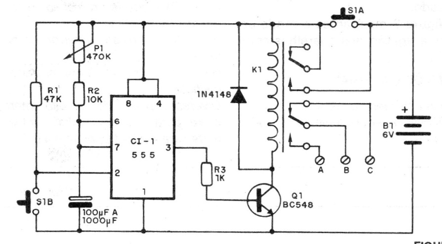
In figure 1 we have the complete diagram of the timer.
In figure 2 we have the printed circuit board.
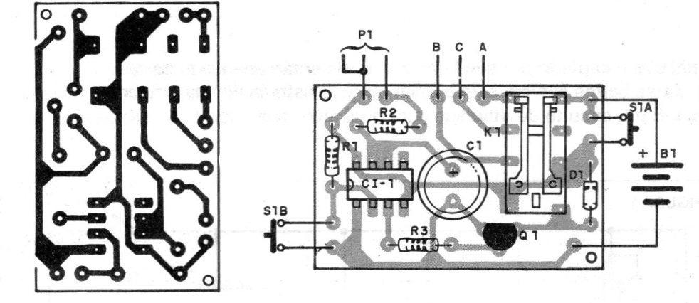
Note that the relay used is of the micro-relay type, which fits directly on the board.
The separation between the connection terminals when making the board must be made with care so that the component can be docked and welded without problems. If you prefer, use a 14-pin DIL integrated socket.
The formula that allows to calculate the maximum time obtained in function of the components chosen is the following:
T = 1.1 x R x C
At where:
T is the time obtained in seconds;
R is the resistance corresponding to the sum of P1 with R2. See that P1 can not be greater than 1M and the value is given in ohms;
C is the capacitance of C1 which must be at most 2 200 uF and expressed in farads (1 Farad = 1 000 000 uF).
For P1 we can use both trimpot and potentiometer, if the control must be external.
Switch S1 is a double pressure type. A pressure switch can be used (range switch for car radio) in the absence of the original type.
An optional element of this circuit would be an LED in parallel with the power supply after S1 that would turn on when the timer is activated. This LED should be connected in series with a 820 ohm or 680 ohm resistor.
For the connection of the external device we recommend the use of a terminal bridge with screws.
TEST AND USE
To test, simply place the batteries in the holder and initially set P1 for the shortest time, ie in the lowest resistance position. Pressing S1 should hear the relay lock closing its contacts, and if there is LED monitor it should light up.
After a few seconds, the relay should turn off and the LED will turn off.
Set potentiometer P1 to maximum and check the time it takes to unlock the relay. If you want, with the help of a stopwatch (or clock), scale with P1 (if potentiometer) to determine the actuation times of the device.
If at greater times the unit refuses to unlock, it is a sign that the capacitor is leaking (C1) and must be replaced.
Figure 3 shows how to connect controlled devices.
MATERIAL LIST
CI-1 - integrated circuit 555
Q1 - 80548 or equivalent - general purpose transistor
D1 - 1N4148 or 1N914 - general purpose diode
S1 - double pressure switch
B1 - 6 V - 4 small batteries
K1 - Sensitive 5 or 6 V Relay
P1 - 470 k at 1M - trimpot or potentiometer
R1 - 47 k - resistor (yellow, violet, orange)
R2 - 10 k - resistor (brown, black, orange)
R3 - 1 k - resistor (brown, black, red)
Miscellaneous: printed circuit board, mounting box, wires, solder, support for 4 small batteries etc.


