
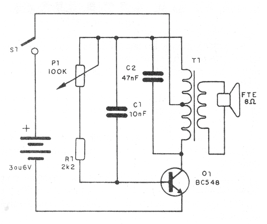
An old output transformer taken from some old transistorized radio that no longer works is the basis of this simple experimental design. It is an audio oscillator, ie a circuit that produces a continuous sound whose frequency is controlled by the potentiometer P1.
The circuit can be powered with 3 or 6 V (2 or 4 small batteries) and the used transistor does not have to be the BC548. Any NPN of general use serves and even PNP if the polarity of the batteries is reversed.
The output transformer can be easily identified in a radio, as it is what is connected to the loudspeaker. In figure 1 we have the oscillator diagram.
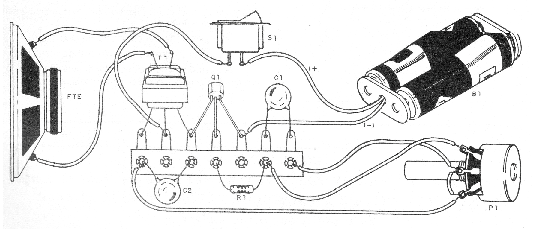
On assembly, observe the position of the transistor and the polarity of the batteries. Eventually C2 must be changed if the circuit does not oscillate properly.
Material list
Q1- Any NPN transistors of general use (BC548)
T1- Transformer output transformer
S1- On-Off switch
B1- 2 or 4 small cells
FTE - 4 or 8 ohms speaker
P1- 100 k ohms - potentiometer
R1 - 2k2 x 1/8 W - resistor - red, red, red
C1 - 10 nF - ceramic or polyester capacitor
C2 - 47 nF - ceramic capacitor or polyester
Miscellaneous: terminal bridge, strip holder, wires, solder, etc.


