
In this circuit, neon lamps light according to the water level in a reservoir. The power consumption is extremely low so that the device can be permanently switched on. Each lamp consumes less than one thousandth of a watt in this circuit.
When water rises or falls, contact with sensors that are stripped wire ends will trigger the corresponding lamp. In figure 1 we have the complete diagram of the detector and also its assembly based on a terminal bridge.
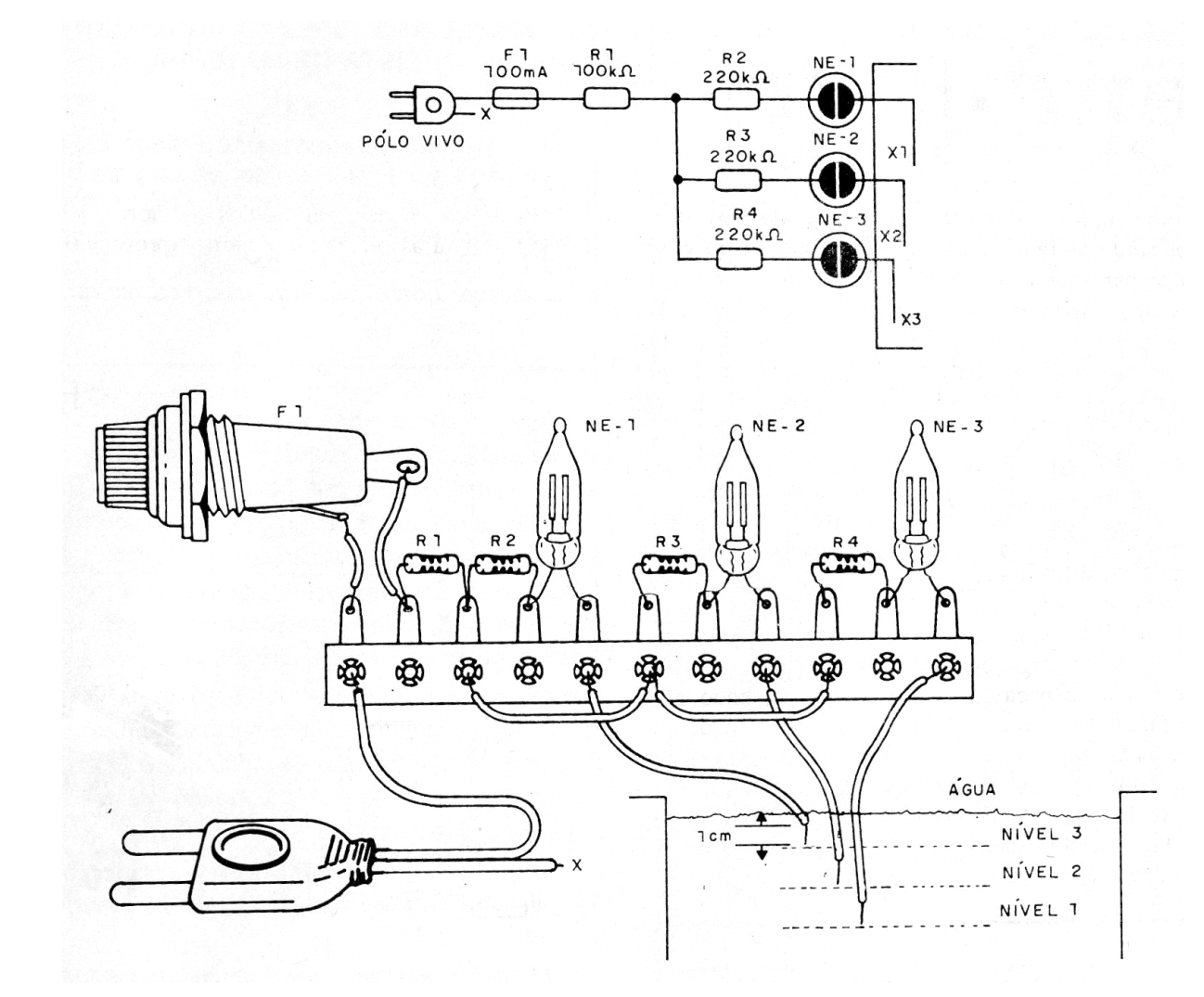
In the example we have three lamps that can indicate a full box, medium level or empty. The connection must be made in one of the poles only of the socket (live pole), since the other pole represents its own contact with the water of the reservoir.
The wires connecting the neon lamps should not be too long, as this will cause the noise to pick up and cause the lamps to light up. Resistors can range from 220k to 470k.
Material list
F1 - 100 mA to 300 mA - fuse
R1- 100k ohm - 1/8 W resistor - brown, black, yellow
R2, R3, R4 - 220k ohm to 470k ohm x 1/8 W- resistors
NE-1 to NE-3 - Common Neon Lamps
Miscellaneous: terminal strip, power cord, fuse holder, wires, solder, etc.


