
This different design uses a coil wrapped in a nail to generate signals in the audio band. These signals can be used in the testing of audio and even RF circuits, given the existence of many harmonics extending to a few dozen megahertz.
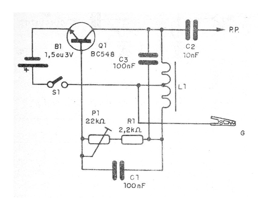
The circuit is powered by one or two small batteries and has a frequency adjustment. In figure 1 we have the complete diagram of the Hartley oscillator that is used in this case.
The coil is formed of 300 to 500 turns of 32 AWG or thinner wire in a nail of 5 to 10 cm in length. The tap is central and care should be taken to strip the wire at the welding point. In figure 2 we have the mounting on a terminal strip.
P1 can be either a trimpot or a common potentiometer and its value is not critical and can be between 22k and 100k. This component adjusts the frequency of the generated signal.
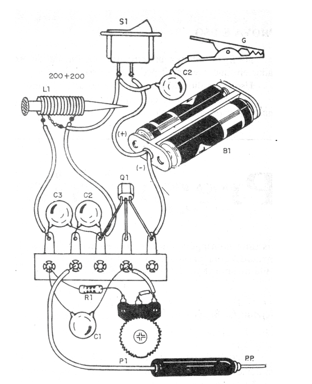
To apply the signal to the circuit under test, we recommend using a probe and an alligator clip.
Material list
Q1 - BC548 or equivalent - General Purpose NPN Transistor
L1 - Nail Coil - see text
P1 – 22 k ohm - trimpot
B1 - 1.5V or 3V - 1 or 2 small batteries
S1 - Single Switch
R1 - 2.2k ohm x 1/8 W - resistor - red, red, red
C1 and C3 - 100 nF - ceramic or polyester capacitor
C2 - 10 nF - Ceramic or Polyester Capacitor
PP - Probe
G - Alligator Clip
Miscellaneous: terminal bridge, nail, enameled wire, wires, welding, etc.


