
This circuit, given in figure 1, makes use of two transistors. The former is used as a white noise generator, and may be of any NPN silicon, general purpose type, or even a commonly used reverse polarized silicon diode.
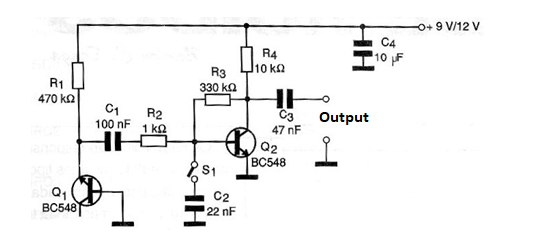
The second transistor functions as an amplifier stage with a good gain in order to obtain an output signal that can be used to excite audio amplifiers. The switch S1, when closed, places the capacitor C2 in the circuit in order to cut the higher frequency components of the generated noise.
This means a reduction in the amplitude of the signal generated with frequency, which characterizes the production of pink noise. The reader can change the value of this capacitor according to the desired attenuation with frequency.
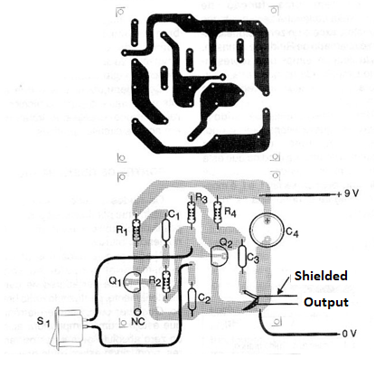
The printed circuit board for this circuit is shown in figure 2.
The circuit is not critical and can be powered with a 9 V battery, since the consumption is very low if the unit is used as an independent source of noise.
If the circuit is added to a more complex design, the power supply can be made with voltages from 8 to 15 V, with the possible need to change R4. R1 can also be tested in the range of 220 k ohm to 1 M ohm.


