
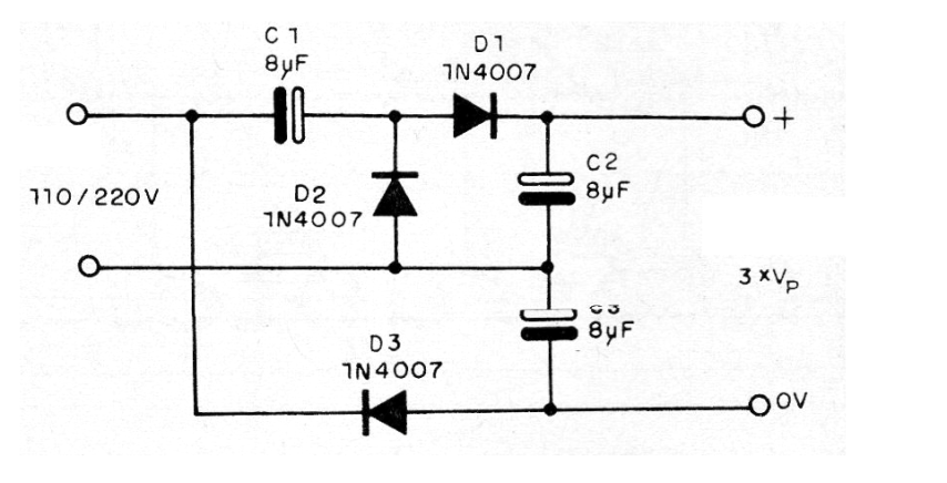
In the 110 V grid we can get from this circuit a continuous voltage of the order of 450 V and in the 220 V grid we can get around 900 V without load. The maximum current is on the order of a few tens of milliamps. What we have is a voltage triple multiplier that multiplies the input voltage of the power grid by 3 and rectifies it to power some electronic circuit.
Capacitors must have a working voltage that is at least twice the peak voltage of the network at which the circuit operates. That means at least 300V for the 110V grid and twice that for the 220V grid. With larger capacitors, we can get a higher output current.
The same circuit also operates at low alternating voltages, in which case the working voltages of capacitors and diodes may also be lower.
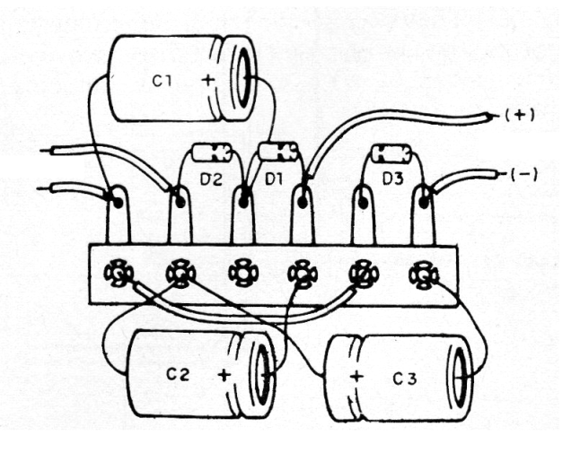
In figure 1 we have the complete circuit of the triplicator and in figure 2 the arrangement of the components in a small terminal bridge.
If the circuit is connected directly to the power grid, connect a 1 amp fuse in series.
Caution: This circuit is not isolated from the power network and may cause dangerous shocks if touched.
Material list
D1, D2, D3 - 1N4007 - Silicon Diodes
C1, C2, C3 - 8 uF x 300 V (110 V) or 8 uF x 600 V (220 V) - Electrolytic Capacitors
Miscellaneous: terminal strip, wires, soldering, etc.


