
Signals with a sawtooth like waveform are typically generated by relaxation oscillators with unijunction transistors, PUTs, SCRs, and other less common semiconductor devices. The circuit we describe in this article operates with common transistors and their frequency can be adjusted over a wide range of values.
The circuit we describe can serve as a time base for a low frequency oscilloscope, such as tone generator for musical instruments or even A / D converters used in digital measuring instruments. Its main feature is in the fact of using ordinary transistors and therefore not be critical and easy to assemble.
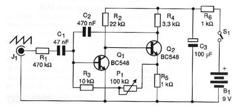
The frequency of the generated signals depends on the capacitor C2 and is adjusted over a wide range of values by P1. For the values of these components indicated in the diagram, the frequency can be adjusted between a few tens of hertz up to approximately 10 kHz. C2 capacitor changes may alter this operating range.
Features:
• Power supply voltage: 9 Vdc
• Typical drain current: 5 mA
• Signal waveform generated: sawtooth
• Frequency range: 10 Hz to 100 kHz
HOW IT WORKS
The two transistors are connected so as to form a high-gain amplifier stage with direct coupling. The feedback of the signal taken from the collector of Q2 via C2 is made to the base of Q1, thus maintaining the oscillations. These oscillations have their frequencies adjusted by P1.
We then obtain at the base of Q1 signals whose waveform is of the sawtooth type, and at the same time, at the collector of Q2, rectangular signals, due to the rapid switching of this second transistor. The signal can be removed from the circuit via C1 and R1 which is intended not to charge the circuit, which would make it difficult to oscillate.
ASSEMBLY
Figure 1 shows the complete diagram of the oscillator.
The few components may be affixed to a printed circuit board with the arrangement shown in Figure 2.
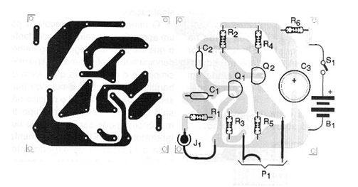
Actually, NP1 general purpose transistors of any type can be used for Q1 and Q2. The resistors are 1 / 8W or larger and the capacitors C1 and C2 can be both polyester and ceramic. The capacitor C3 · of the electrolytic type with a working voltage of 12V or more. The power supply can be made by a small source or battery, since the consumption is not high.
For signal output, if the instrument is used as a benchtop generator for general testing, a P2 or RCA type jack can be used. Another possibility is to use two wires with alligator clips
USE
The verification of the waveform produced must be done with an oscilloscope, but to know simply if the circuit is oscillating simply connect its output at the input of any audio amplifier or even a common piezoelectric transducer or high impedance headphone. Once the operation is confirmed, use the appliance only.
MATERIAL LIST
Semiconductors:
Q1, Q2 - BC548 or equivalent - general purpose transistors
Resistors: (1 / 8W, 5%)
R1 - 470 k ohm - yellow, violet, yellow
R2 - 22k ohm - red, red, orange
R3 - 10 k ohm - brown, black, orange
R4 - 3.3 k ohm - orange, orange, red
R5, R6 - 1k ohm - brown, black, red
P1 - 100 k ohm - potentiometer (or trim-pot)
Capacitors:
C1 - 47 nF (473 or 0.047) - ceramic or polyester
C2-470 nF (474 or 0.47) - ceramic or polyester
C3 - 100 uF / 12V - electrolytic
Several:
J1 - RCA jack
S1 – On/Off switch
B1 - 9V - battery or power supply
Printed circuit board, mounting box, battery connector, potentiometer knob, wires, solder, etc.


