
The circuit of Figure 1 is suggested by National Semiconductor and can generate signals from 700 Hz to 100 kHz when the input or control voltage ranges from 250 mV to 50 V.
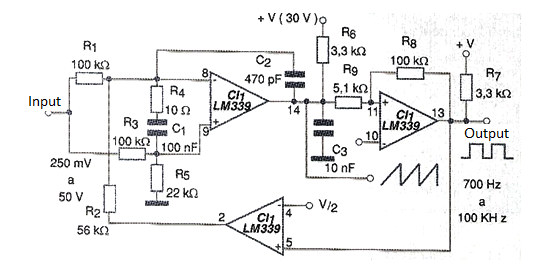
Three of the four voltage comparators on the LM339 integrated circuit are used. The time capacitors can be changed to generate other voltage ranges.
The power supply is made with a single 30 V supply, observing that the V / 2 reference at the inputs of two comparators can be obtained with a splitter consisting of two 10 k ohm resistors. The circuit provides rectangular and triangular signals at two different outputs.
Note that 3.3 k ohm pull-up resistors are required at the comparator outputs to ensure proper polarization of their outputs, as they use open collector resistors.
In figure 2 we have a suggestion of printed circuit board for the assembly of this oscillator.
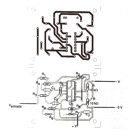
Of course this configuration can be changed according to the design needs, with the exchange of comparators used in each stage.
Material list
CI-1 - LM339 - Quad Voltage Comparator
R1, R3, R8 - 100 k ohm x 1/8 W - resistors
R2 - 56 k ohm x 1/8 W - resistor
R4 - 10 ohm x 1/8 W - resistor
R5 - 22 k ohm x 1/8 W - resistor
R6, R7 - 3.3 k ohm x 1/8 W - resistors
R9 - 5.1 k ohm x 1/8 W - resistor
C1 - 100 nF - capacitor
C2-470 pF - capacitor
C3-10 nF - capacitor
More:
Printed circuit board, 30 V power supply, wires, solder, etc.


