Any movement that swings the pendulum sensor tríggers this alarm, enabling a relay.
The circuit can be used to protect cars, large objects, homes and other places as the sensor can be used to detect any movement
This device can also be used for scientific experiments, as suggested at the end of the section.
The relay can drive powerful sound systems, such as sirens, horns, lamps, etc. The circuit can be powered by a 12-volt battery (when used in cars, for instanoe) or a power supply.
Current drain is very low (about 100 µA) when the relay is deenergized, extending battery life.
The schematic circuit of the Pendulum AIarm is shown in Figure 1.

The circuit has as its heart an SCR (Silicon Controlled Rectifier), which energizes the relay when the sensor detects any movement.
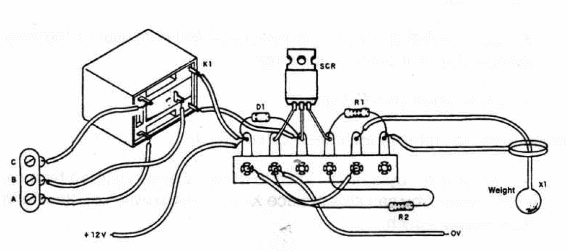
A mechanical view of the circuit mounting, using a terminal strip as chassis, is shown in Figure 2.

Relay coil voltage is chosen according to the power supply voltage. You can use a mini DPDT 1A Minii Relay (Radio Shack 275-249) or, for heavy loads, a 10 A mini SPDT relay (Radio_ Shack 275-248). These relays are rated to 12 VDC and drain only 38 mA (their coil resistance is about 320 Ω).
As equivalent types can be used, you should take care with terminal layout.
Reset can be made with a momentary-type switch (Push-On) wired between the SCR anode and catode. or by using the on-off switch.
Positions of polarized components, such as the SCR and diode, should be observed.
Sensor details are also given in Figure 2. Notice that operation occurs when the vertical (or horizontal) bare wire touches the ring during any movement.
Pendulum Alarm
SCR - TIC106 or equivalent Silicon Controlled Rectifier
D1 - 1N914 or equivalent generaI-purpose silicon diode
K1 - 12V relay (see text)
S1 - SPST slide or toggle switch
R1 - 22,000 ohm, ¼ W, 5% resistor
R2 - 10,000 ohm, ¼ W, 5% resistor
X1. - Pendulum sensor›(see text)
Ideas to Explore
To learn more about circuit and devicesz
Replace relay with a 12V x 200 mA incandescent lamp. Does the circuit work?
Explain what D1 ís doing in this circuit ls it necessary if the relay is replaced by an incandescent lamp?
Explain how an SCR works.
Science projects and different uses fofthis circuit
Replace X1 by a reed switóh to get an alarm triggered Iby a magnetic sensor.You can also replace X1 bva microswitch or other kind of momentary switch.
ln biological experiments the alarm can be used to detect small movements in animal traps or cages.
O Replacing X1 by two metal wires enables the circuit to be triggered by water. Water Ievel detectors can be made using this kind of sensor,
and it can be used in many experiments and practical applications.
Installed in your car, this circuit can be used as an alarm, driving the horn or a siren.
By replacing X1 with a large metal plate, the circuit can be used to detect wind. Air flow can move the plate so that the bare wire touching the Ioop causes the alarm to trigger.
Obs. This circuit is part of the author’s book Fun Projects for the Experimenter – TAB Books – 1998


