This circuit imitatest the sound of wet bugs milling about the surface to attract curious fish.
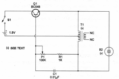
The circuit is basically a Hartley audio oscillator operating in a frequency between 200 and 2,000 Hertz.
Powered by an AA cell, it can housed in a clean empty peanut butter jar with the buzzer circuitry mounted upside-down on the cover.
You must be carefull not to drill in such a way as to allow water to Ieak through the cap.
Silicon rubber can be used to close any water leak.
Capacitor C1 would give a resonant frequencytof approximately 1,000 Hz, but P1 would give a wide variation in signal tone generated in the audio range.
You can also use a !ow impedance earphone as à transducer, connecting it to the second coil (output) of the transformer.
To operate, unscrew the cap throw S1 ON, put the cover back on, and drop the fish Iure into the water in the vicinity of where you will be fishing.
Allow 20 minutes before reeling them in. If necessary, adjust P1 to a new signal tone.
Figure 1 shows the schematic diagram for the Fish Lure.

Observe that the secondary coil of the small audio transformer is not used in this circuit.
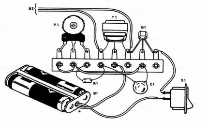
Construction details of the Electronic Fishing Lure, using a terminal strip as chassi is shown in Figure 2.

The exact locations of components is not critical.
T1 is also not critical Any 500:8 or 1,000:8 transistor transformer with center-tapped primary can be used.
We can also suggest that any small transistor transformer can be experimented with.
Electronic Fishing Lure
Q1 - BCS48 generaI-purpose NPN silicon transistor
T1 - 500:8 or 1,000:8 transistor transformer (RadioShack 273-1380 is suitable for this task)
P1 - 100,000 ohm trimmer potentiometer
R1 - 1,000 ohm, ¼ W, 5% resistor
C1 - 0.01 µF metal film or ceramic capacitor
S1 - SPST toggle or slide switch
BZ - Piezoelectric transducer or crystal earphone (Radio Shack273~073 or equivalent)
B1 -1.5 V AAceIl
Ideas to Explore
To Iearn more about the circuit
Replace BZ by a Iow-impedance tweeter or smaII Ioudspeaker connected to the transformer secondary coil.
Change C1 values in the range between 0.001 and 0.22 µF. Observe what hapens with tone pitch. A higher-value, capacitor gives a Iower tone.
The circuit also operates from a 3V or 6V power supply without making any changes.
Science and different uses for the device:
You can make several experiments in animal conditioning, including the ones that Iive in the water. Try to alter the RC network (P1, R1 and C1) to get tones of different pitch. Try to use diodes, small transformer coils and other passive components in this experiment. Sounds Iike those produced by songbirds can be generated with a few components arranged in the correct way. Can you discover how to do it?
Remove the piezoelectric transducer and wire electrodes in its place. The device canbe use as a nerv stimulator. Experiments with animals and plants can be made. What physiological functions are affected? Can circadian. rhytms or internal biological cIocks be affected by continuous exposure to sounds?
Electrodes placed into water and wired in place of the transducer will produce a current field.You can perform interesting scientific work relating how fish and other water beings react to the current field. Can the current fields affect physiological functions? If you experiment with plants, select a fast growing house plant.
Note: This circuit is part of the author’s book Fun Projects for the Experimenter – TAB Books – 1998


