In order to perform experiments and projects involving electricity you wiII need a source of voltage.
Voltage requirements for common projects, such as the ones in this book, depend upon their applications, and typically range from a few milliamperes to one or two amperes.
Instead of using a battery you can use a circuit called a power supply.
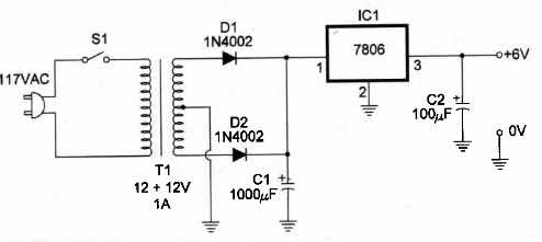
The power supply we show here can be used to provide 6 V x 1A regulated output to the experimental and practical circuits described in this book. The output voltage is fixed by the IC.
Figure 1 shows the schematic diagram for this power supply.

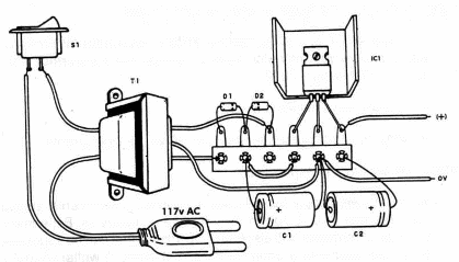
Figure 2 shows the components layout, using a terminal strip as chassis.

The complete project can be assembled in a small plastic box. The integrated circuit should be mounted on a heatsink.
You can also add an LED in series with a 470 ohm resistor, wired in the output of the circuit to indicate that it is on.
Extemal circuits can be connected to the power supply with aIIigator clips.
Position of the polarized pieces, such as diodes, the lC, and electrolytic capacitors, must be observed.
The transformer isn't a critical part of this project. Types with a secondary coil ranging from 7.5 to 12 volts and currents between 500 mA and 1A can be used.
You also can use a transformar with a 220/240 Vca if that is the voltage in the place where you live.
6-Volt Power Supply
IC1 - 7806 positive three-terminal regulator
T1 - Transformer: primary 117 VAC ; secondary 12+12V x 1A
D1, D2 – 50 V x 1A - 1N4002 or equivalent silicon rectifier diodes
C1 - 1,000 µF, 25 WVDC electrolytic capacitor
C2 - 10 µF, 12 WVDC electrolytic capacitor
S1 - SPST switch
Ideas to Explore:
To learn more about the circuit or alter the performance:
Replace IC1 by a 7805, 7809 or 7812 if you want a 5 V, 9 V or 12 V power supply. You may also have to change the transformer with a 117:15+15V using a 7812.
Explain how the circuit works.
What is the difference between an AC and at DC current?
Scíence and uncommon applications:
This power supply can be used in chemical experiments, such as the ones that involve current flow through substances. Experiments involving electrolysis and electroplating are two that can be suggested. A variable wound-wire potentiometer (1OO Ω, 5 watts) should be wired in series with the power supply output to Iimit cu rrent flow th rough the Ioad.You can also use the Light Dimmer described in this site for this task.
6V, 200 mA small incandescent lamps can be supported by this power supply. These hamps are excellent light sources to work with microscopes.
Small motors and lamps in experiments involving physics, mechanics and robotics can be powered from this power supply with advantages. You don't have to spend a lot of money on cells or batteries.
Many circuits described in this section and the site which require a 6V supply can be powered by this power supply.
The circuit can be used as an excellent power adapter for your 6V equipment, such as small radios, calculators, etc. o 6V Iamps can be used in experiments involving plant growth. SeIect a fast growing house plant and use a darkroom or cardboard box to cover them. Lamps with colored filters can be used in an experiment involving growth and development.
Circadian rhythms can also be studied using animals or plants. Lamps or LEDs can be powered on at night and off at day. What physiological functions could be affected?
Note: This circuit is part of the author’s book Fun Projects for the Experimenter – TAB Books Vol 1 – 1998


