Some continuous sounds can repel insects (and also attract). The frequency and intensity depends upon the application and type of insect and can be found through experimentation.
The circuit shown here generates a continuous sound that can be used to repel (or attract) some types of insects, or in scientific experiments involving animals.
Our insect repellent can be powered by 9V' batteries, two AA cells or four AA cells, and its Iow current requirements wilI extend the life of those cells or batteries.
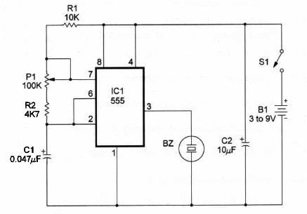
Figure 1 shows the schematic diagram of the lnsect Repellent.

The heart of the circuit is a 7555 IC, a CMOS timer wired as an audio oscillator and driving a piezoelectric transducer.
The components plaóement on a homemade printed-círcuit board is shown in Figure 2.

Exact placement is not that critical.
AII the components and the power supply can be housed in a small plastic box.
Transducer BZ is a crystal earpiece or a piezoelectric transducer, such as the
Radio Shack 273-073.
Position of the polarized pieces, such as 02 and the power supply, must be carefully observed.
Using the insect repellent is very easy. You onlyneed to adjust the trimmer potentiometer P1 to produce a sound with the same pitch as the insect you íntend to repel.
Experimentation should be made until you find the best sound to repel a specific insect
Insect Repellent
C1 - TLC7555 CMOS integrated-circuit timer
BZ - Crystal or piezoelectric transducer Radio Shack 273-073 or equivalent
R1 - 10,000 ohm, ¼ W, 5% resistor
R2 - 4,700 ohm, ¼ W, 5% resistor
P1 - 100,000 ohm trimmer potentiometer
C1 - 0.047 µF metal film or ceramic capacitor
C2 - 10 µF, 12 WVDC electrolytic capacitor
S1 - SPST slide or tóggle switch
B1 – 3 V (2 AA cells), 6 V (4 AA cells), 9V (battery)
Ideas to Explore
To Iearn more about the circuit or get better performance:
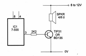
Powerful output can be obtained with a transistorized output stage as shown in Figure 3. The power transistor should be mounted on a heatsink. The transducer is a low-impedance Ioudspeaker ranging from 4 to 8 Ω.

Experiments with ultrasound cah be made with this circuit reduce C1 to 1200 pF and use a piezoelectric tweeter as transducer. Remove the small transformer used in these tweeters and plug the transducer directly to the circuit output Outputs in frequencies as high as 40,000 Hz can be produced by this circuit.
Explain how sounds can be produced by electronic transducers such as the one used in this project.
o What are ultrasounds?
Science and different applications:
Of course, you can test the real effects of this device on severa! kinds of insects. An attractive biological experiment can be conducted based on this circuit.
Effects of sounds on plant growth or development can be conducted using this circuit. Can sounds (Qr ultrasounds) alter the circadian rhythms of plants and insects?
The continuous tone produced by this circuit can be used in alarms or warning systems. Mice and other smaII animals are repelled by powerful ultrasounds.
Replace R2 by an LDR. The circuit now becomes a Iight-dependent oscilaaton Experiments with Iight and sounds can now be conducted using the device.
Note: This circuit is part of the author’s book Fun Projects for the Experimenter Vol1 – TAB Books – 1998


