This audio controlled relay has a Iarge number of applications and is interesting to the experimenter who wishes to explore the working universe of reIays and audio or sound controlled circuits.
An audio signal in the amplitude range between 1 Vpp and 5 Vpp triggers the reIay, powering on the device, wired between points A and B.
Relay value is determined by power supply voltage. For a 12 volt power supply you must use a 12 voIt reIay.
Current drain depends upon the power supply voltage and also the relay sed.
Using a 12V x 38 mA (Radio Shack 275-248) reIay, the current drain is Iow enough to allow the use of common cells in the power suppIy.
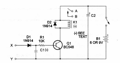
C1 can range between 0.01 and 1.0 µF, and determines the sensitivity of the circuit in the audio range.
Large values give more sensitivity at Iow frequencies.
This circuit has a high-impedance input and needs a strong audio signal to operate.
Figure 1 shows the schematic diagram of the Audio Switch.

Observe that the heart of the circuit is a oommon generaI-purpose NPN transistor that acts as a DC amplifier.
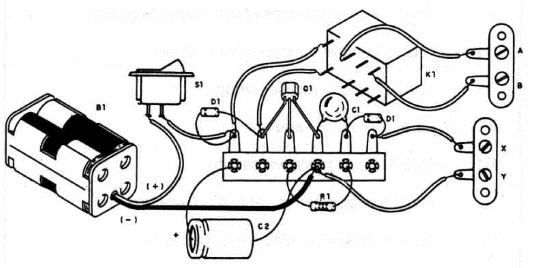
ln Figure 2 we show Iayout of components for this project

The components can be soldered on a terminal strip used as chassis.The terminal strip can be fixed on a wooden board.
Position of the poIarized components, such as the diodes, power supply and capacitor C2, must be observed.
To use this audio relay you have to wíre ponts A and B to the output of an audio amplifier (minimum power required is 5 watts) and adjust the volume control for best operation.
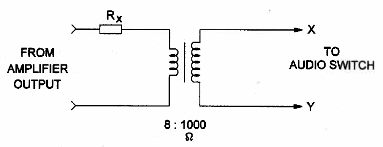
A smaII transistor output transformer should be used to operate the relay with low-impedance signals, such as the ones from the output of audio amplifiers.
Figure 3 shows how to use this transformer.

Rx depends on the output power of the amplifier and is given below:
0 to 1 watt
1 to 10 watts 47 Ω, 1/4 watt
10 to 25 watts 100 Ω, 1/4 watt
25 to 50 watts 220 Ω, 1/2 watt
Audio Switch
Q1 - BCS48 generaI-purpose NPN silicon transistor
D1 -_ 1N914 general purpose silicon diode
D2 - 1N4002 silicon rectifier diode
K1 – 6 V or12 V relay - sée text
R1 – 10,000 ohm, ¼ W, 5% resistor
C1 - metal film or ceramic capacitor - see text
C2 - 100 µF, 12 WVDC electrolytic capacitor
B1 – 6 V or 12 V cells, power supply or battery
Ideas to Explore
To Iearn more about the circuit and devices or to get better performance:
Replace Q1 with a Darlington transistor (such as a BCS17) and resistor R1 with 100,000 Ω. The circuit will increase in sensitivity.
Explain how C1 functions in this circuit.
Science and different applications
Connect the circuit to an audio amplifier output, with a microphone plugged to the amplifier input. You'Il have a sound-operated switch.
o This circuit with a microphone and an audio amplifier can be used to close a trap with sound activation or to activate a recording with sounds. You can also use it to photograph an explosion or the crash of an object by triggering a flash with the produced sound.
The audio output of a multimedia system in a Computer can be used to control external devices with this circuit.
Note: This circuit is part of the author’s book Fun Projects for the Experimenter Vol1 – TAB Books – 1998 (link para download)


