These circuits have always been popular for both utility and entertainment purposes.
The FM transmitter described here is built with few components to save space and cost.
The circuit has only one transistor and is powered by two or four AA ceIIs.
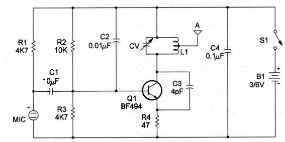
The broadcasting frequency of the unit, in the range between 88 and 108 MHz (FM band), is determined by L1 and the variable capacitor CV (a 20 or 30 pF trimmer capacitor).
L1 consists of four turns of No. 22 wire, wound in a single cIose-spaced Iayer on a 1/2-inch form.
The coil is center tapped where it is wired to the antenna terminal.
Any piece of stiff wire will serve as the antenna and will give good coverage.
For better operation, antenna Iength should be between 5 and 15 inches.
Try out your unit at any convenient dead spot on the FM band.
Adjust CV to the best signal. The signals can be tuned in distances up to 150 feet.
A schematic diagram of the FM transmitter is shown in Figure 1.

Only one transistor as used as a highbfrequency oscillator.
Any low power RF NPN transistor can be used for the task.
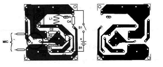
Components placement on a printed-circuit board is shown in Figure 2.

Capacitors are critical components and should be the types indicated in the parts list.
Don't use metal film capacitors instead of the ceramic capacitors which are called for in the parts list.
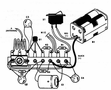
You can also use a terminal strip as chassis as shown in Figure 3,

The circuit can be housed in a small plastic box along with the power supply.
Avoid the use of metal boxes to house the circuit Take care with position of the polarized pieces, such as the electret microphone, electrolytic capacitor and power supply.
Wereless FM Transmitter
Q1 - BF494 RF silicon transistor
MIC - two-terminal electret microphone
L1 - coil - see text
CV - trimmer capacitor (20 to 50 pF)
R1, R3 – 4,700 ohm, ¼ W, 5% resistor
R2 – 10,000 ohm, 1/4w, 5% resistor V
R4 - 47 ohm, 1/4W, 5% resistor
C1 - 10 µF, 6 WVDC electrolytic capacitor
C2 - 0.01 µF ceramic capacitor
C3 - 4.7 pF ceramic capacitor
C4 - 0.1 µF ceramic capacitor
S1 - SPST slide or toggle switch
B1 – 3 V or 6 V - two pr four AA cells
A - antenna -~see text
Ideas to Explore
To Iearn more about the circuit or to get better performance:
Replace transistor Q1 with a 2N2218 and power the circuit from a 9 V battery. The signals wiII be tuned in from distances up to 1,500 feet.
The circuit can be used as a “bug” to hear secret conversations.
Place the circuit inside a false book on a desk to pick up conversations.
Explain how the transmitter works.
What are radio waves or electromagnetic waves?
What is Frequency Modulation (FM) and Amplitude Modulation (AM)? Explain the differences.
Science projects using this transmitter:
The transmitter can be used to pick up remote sounds. You can fix it in animal pens or jails to monitor them remotely.
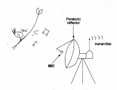
The mike can be placed in the focus of a parabolic reflector to concentrate sounds. Birds and other animals in the forest or other places can be heard using this system, as suggested in Figure 4. An interesting study can be made involving Iocal songbirds.

You can use this transmitter for an experimental broadcast in your schooL However, don't use Iong antennas because FCC rules are severe regarding strong illegal radio emissions ín the FM band.
Note: This circuit is part of the author’s book Fun Projects for the Experimenter Vol1 – TAB Books – 1998 (link para download)


