Small appliances, lamps and motors can be controlled by a simple touch with this experimental circuit.
Loads are ON during the time adjusted by P1 for a few seconds to more than 10 minutes. Conversely, by using the NC (normally closed) contacts you can also turn off an appüance after the adjusted time.
The sensor is formed by two small metal plates, and shouldn't be placed far from the circuit.
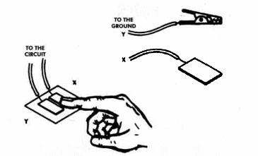
The metal plates are finger-touched at the same moment.
The circuit can be powered from a 6-volt or 12-volt power supply, depending on the relay used.
Do not use transformeless power supplies with this project, to avoid shocks or dangerous shorts.
Transformer less power supplies are not isolated from the AC power Iine and represent a dangerous shock hazard.
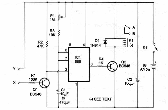
K1 is a relay with 6- or 12-volt coil and is energized by current up to 50 mA.
With relays in this range you can power the touch switch from AA cells (6 volts) or small power supplies.
A schematic of the Touch Switch is shown in Figure 1.

The circuit uses a 555 IC timer as its heart, and time delay is determined by adjusting P1.
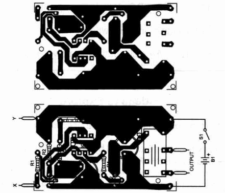
Circuit mounting, using a small homemade printed-circuit board, is shown in figure 2.

If you'd Iike to etch your own board use this parts placement diagram as guide.
In Figure 3 we show the sensor that can be made with two small metal plates on a plastic or wood base.

Wires to the sensor shouldn't be Iong.
A maximum lenght of 10 feet is recommended to avoid erratic operation.
Position of the po!arized components, such as the electrolytic capacitors and diodes, should be observed.
Load is connected to terminals A and B. Remember that the relay acts as a switch.
Don't power this circuit from transformerless power supplies to avoid dangerous shocks and shorts.
A sensitivity control can be added to this circuit in a simple manner. Use a 1,000,000 ohm potentiometer for this task.
Touch Switch
IC1 - 555 integrated circuit, timer
Q1, 2 - BCS48 generaI-purpose NPN transistors
D1 - 1N914 silicon diode
K1 - relay - see text
R1 - 100,000 ohm, ¼ W, 5% resistor
R2 - 47,000 ohm, ¼ W, 5% resistor
R3 - 10,000 ohm, ¼ W, 5% resistor
R4 - 1,000 ohm, ¼ W, 5% resistor
P1 - 1,000,000 ohm, ¼ W, 5% resistor
C1 - 10 to 470 µF, 12 WVDC electrolytic capacitor - see text
02 - 100 µF, 16 WVDC electroch capacitor
S1 - SPST toggle or slide switch
B1 - 6 or 12 V - AA cells, battery or power supply
Ideas to Explore
To get more performance or to Iearn more about the circuit:
Sensitivity can be increased by replacing Q1 with a Darlington transistor, such as a BCS17.
By connecting a reed switch between points Y and X you can use this circuit do detect movement. Fix a small magnet on the piece to act on the reed switch.
Science and uncommon applications:
This circuit can be used to close a,trap. The touch sensor wiII detect when the animal enters the trap.
Projects that need a way to detect movements, switching any load, can be made with this circuit. Several kind of sensors, Iike microswitches pendulum sensors or any other momentary-type switch can be used in this circuit.
Connect an LDR between points A and B. Also connect a 100,000 ohm potentiometer between X and the negative pole of the power supply. You'll have a Iight-operated relay or remote controL A flash of Iight produced by a lantern or even a cigarette Iighter can close the relay, powering the Ioad. The circuit can be used to detect flashes of light in science experiments. le the LDR into a telesoope and you can detect meteor llings.
Experiments involving thunderstorms at night can be conducted automatically using this circuit. The first flash of lightning can be used to power ON the equipment.
Note: This circuit is part of the author’s book Fun Projects for the Experimenter Vol1 – TAB Books – 1998 (link para download)


