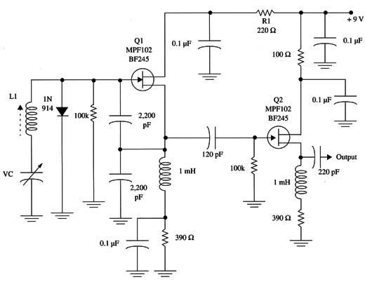
A VFO can be used as the basic oscillator of a transmitter. The circuit shown in Fig. 1 produces high-frequency signals covering a wide range of frequencies whose values depend on CV and L1.

Using a coil formed by 60 turns of AWG 28 wire on a ferrite core (1 cm dia. and 10 cm long), the circuit will produce signals in the range of 2 to 4 MHz.
By reducing the number of turns to 10 or 12, it is possible to reach the upper frequency limit of approximately 10 MHz.
The signal produced by the first FET is applied to the second FET, where it is amplified again. The second FET acts as a buffer thereby isolating the oscillator stage from the output stage and increasing stability.
The capacitors used in the circuit must be appropriate for high-frequency applications such as ceramic or polycarbonate types. The circuit must be powered by a regulated power supply.


