
ART2260S ART160
Encoders and decoders are circuits that transform information obtained in a certain way into another form of code that can be used by subsequent circuits. Since the code transformations that occur most frequently in digital circuits involve the passage of signals from binary to digital form and vice versa, the terms encoders and decoders are specific to these types of signals.
Thus, we call encoders the circuits that transform signals obtained in decimal form into binary or BCD (Binary Coded Decimal) signals, or signals obtained from 16 inputs into signals encoded in hexadecimal, while we call decoders the circuits that convert binary or BCD signals into decimal signals or other types, such as hexadecimal, or even those capable of exciting a 7-segment display. Let us analyze the two types of circuits.
ENCODERS
We can simply define an encoder circuit as a circuit capable of converting a signal of a certain type, such as decimal, into a digital or BCD signal. Thus, if we have 10 activation switches or 10 different signal inputs representing values between 0 and 9, an encoder, such as the one shown in Figure 1, will convert these signals into BCD.
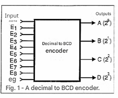
In this system, we have 10 inputs and 4 outputs, obtaining logic levels according to the following truth table:
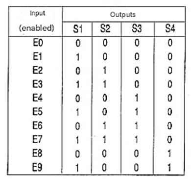
Note that in this table, the output representing the least significant digit (LSB) is S1, while the output representing the most significant digit (MSB) is S4. Thus, the "weights" of the outputs in this table and those given as examples in this article are:
S1 = 1
S2 = 2
S3 = 4
S4 = 8
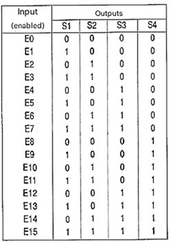
Similarly, we can have an encoder circuit that converts the signals from 16 inputs into signals corresponding to hexadecimal information.
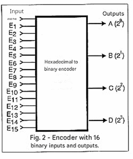
The truth table for such an encoder shown in Figure 2 will be:
A practical encoder circuit can be obtained either using logic gates or a diode matrix. The process using a diode matrix is the simplest to understand because its structure visually corresponds to the truth table itself. Thus, for the case of decoding 10 inputs into BCD outputs, we can create the matrix shown in Figure 3.
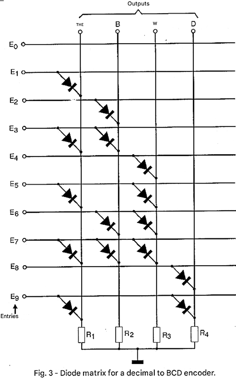
Therefore, what we need to do is simply place a diode on the lines where we need a logic level 1 and not place any diode on the lines where the logic level should be 0. This means that on the lines where we have the diode, when the input goes to a high level, the current can flow, thus producing an output voltage (high level) across the corresponding load resistor, as shown in Figure 4.
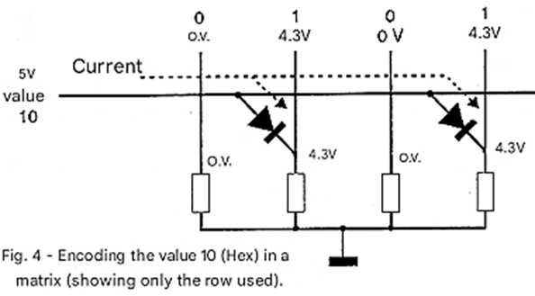
It should only be considered that in this circuit, using silicon diodes, we have a voltage drop of around 0.7 volts at the output, which must be compensated for. Note that, with this type of circuit, it is possible to "program" the encoder to have digital outputs of any combination from an input. Thus, as shown in Figure 5, nothing prevents us from having a completely different sequence from the conventional one for encoding a 4-input circuit.
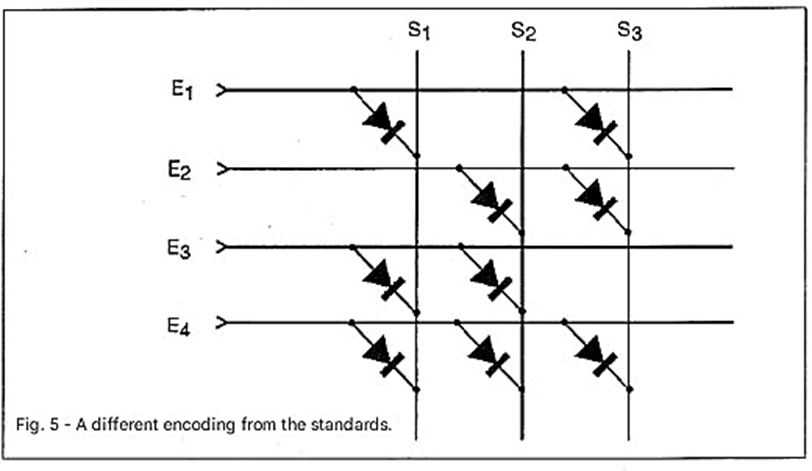
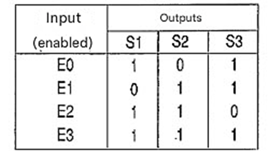
In this circuit we have the following truth table:
Integrated circuits that combine this function in both TTL and CMOS logic are available, but we will discuss them later.
DECODER
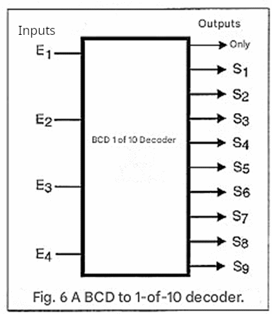
By our definition, a decoder circuit does exactly "the opposite" of an encoder, converting a set of BCD, binary, or other signals normally used by digital circuits into decimal form or another form appropriate for driving a display. Figure 6 shows what would be a 4-input decoder block operating in binary that provides a 10-digit output.
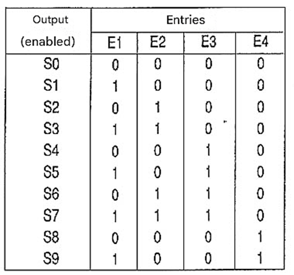
The truth table for a decoder circuit of this type would be as follows:
This circuit can be easily implemented using logic gates, as shown in Figure 7.
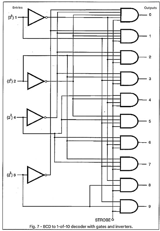
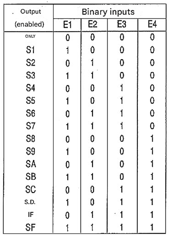
As we can see, the circuit for BCD to decimal decoding with "one of 10" activated outputs uses both AND gates and inverters. An important feature of this circuit is that it has a STROBE input that prevents the circuit from operating when there is an illegal combination of input states, since we only have BCD decoding and not hexadecimal. Thus, if the combination 1011 appears at the input, the circuit is inhibited. For hexadecimal decoding we will have the following truth table:
Another type of decoder widely used in electronic projects involving displays is the BCD to 7-segment decoder. As shown in Figure 8, 7-segment displays can form digits from 0 to 9 and some other symbols by lighting up a combination of 7 light-emitting diodes or LEDs.
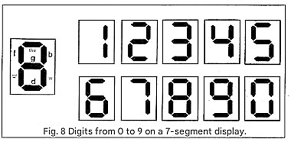
Thus, what we need to do is input the BCD signals into the appropriate circuit and obtain at the output the levels that activate the segments corresponding to the digit that should appear. A truth table for the digits 0 to 9 would be as follows:
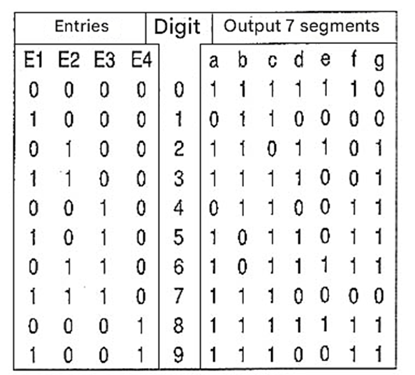
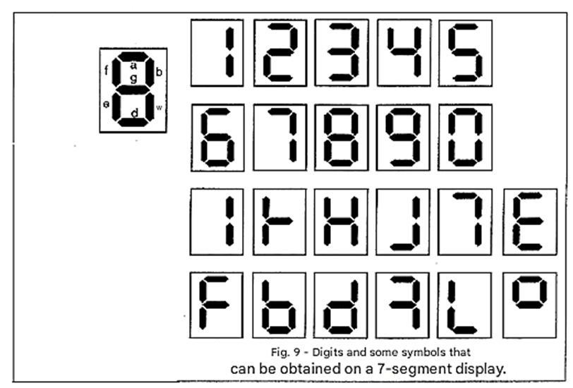
Note that the maximum consumption condition of the display occurs when we have the digit 8 because all digits are lit. For a hexadecimal circuit we could have the additional conditions shown in Figure 9.
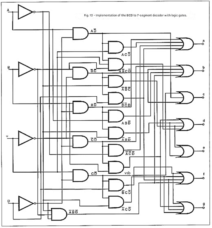
To implement the circuit capable of performing the decoding, we can use gates in a configuration shown in Figure 10.
In practice, integrated circuits containing these functions need to be able to drive higher current loads than those normally corresponding to the inputs of other logic circuits in the same family. Thus, integrated circuits containing these functions are usually equipped with buffers that, in some cases, can even supply high currents at voltages different from those normally used by the same family. In fact, although they are no longer found, as frequently today, there was a time when gas and filament displays were used with these circuits.
In gas displays, there was a high-voltage circuit that ionized the segments to be activated so that they "appeared" lit, while in RCA's Numitron displays, the segments were tungsten filaments mounted on an insulating base in the arrangement corresponding to common 7-segment displays. When an intense current passed through them, these filaments lit up. Within the TTL family, for example, we still find decoders designed to drive such displays in manuals. Today, however, the most commonly used displays are LED or electroluminescent displays that only require external current-limiting resistors.
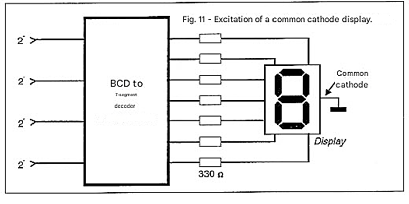
Note also that in the circuit we provided, the decoder outputs go high in the segment that should light up. This means that the corresponding LEDs that light up must have their anode connected to the decoder output and their cathode to ground. As shown in Figure 11, these decoders require displays of the type where all the cathodes of the display are connected to ground. We say that such decoders are for common cathode displays.
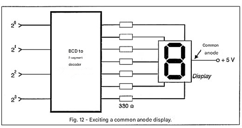
In contrast, there are decoders for common anode displays, that is, where the segments are activated when the corresponding output goes low, as shown in Figure 12.
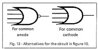
The decoder circuit for such displays can be exactly the same as the one we gave as an example in Figure 10, with the only difference being that we would either add inverters to the outputs or use NOR gates instead of OR gates at the output, as shown in Figure 13.
EXAMPLES OF ENCODER/DECODER INTEGRATED CIRCUIT BREAKERS
In TTL and CMOS manuals, practically no distinction is made between encoders and decoders. Both types of circuits are usually referred to interchangeably as "decoders".
Here are some examples:
TTL:
7442 - BCD to decimal decoder
7445 - BCD to decimal decoder with driver
7447 - BCD to 7-segment decoder with 30 V x 40 mA output
74145 - BCD to decimal decoder with 15 V output
CMOS:
4028 - BCD to decimal decoder
4027 - decoder counter with 7-segment output
4017 - decoder counter with 1 of 10 output


