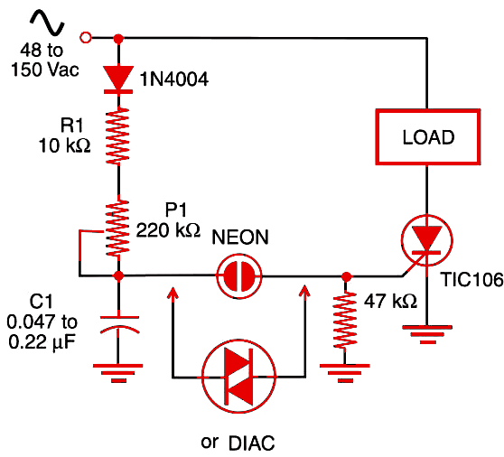
When a half cycle of the ac power voltage begins, the voltage rises at the same time that C1 charges across potentiometer P1 and resistor R1. The time constant of these components is chosen to fall within the time interval corresponding to a half cycle. This means that the SCR will trigger at a point of the half cycle that depends of the adjustment of P1. If P1 is adjusted for low resistance, the time constant is short, and the voltage to trigger the SCR is reached quickly. The SCR turns on at the beginning of the half cycle, allowing almost all of the power to go to the load.

On other hand, if P1 is adjusted for a high resistance, the voltage to trigger the SCR on will be reached only at the end of the half cycle, and the power that passes to the load will be low. Notice that the SCR turns off again at the end of each half cycle of the power supply voltage.
From the lowest resistance point to the highest, it is possible to control the power applied to the load over a large power range. Although this kind of circuit is very efficient when controlling resistive loads, it also is inconvenient in some ways:
1. The fast on and off switching of the SCR can generate noise. The noise can travel through the power supply line or be radiated in the form of electromagnetic waves. In many cases, you will need to use of filters to avoid problems.
2. Only the positive half cycles are controlled.
If the circuit is powered from the ac power line, some kind of device can be added to speed up the triggering process of the SCR. This device can be a neon lamp or a diac in the gate, as shown by the figure.


