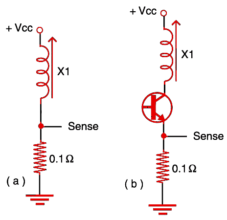
In Figure 1a, we have direct sense. The output is 0.1 V per ampere. In 1b, we have the same circuit when the solenoid is driven by a transistor (bipolar, Darlington, or power CMOS). The value of Rx can be increased according to the application, but remember that, as the value becomes higher, so does the voltage drop in the component and the amount of heat it generates.

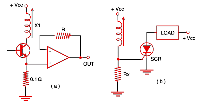
The circuit shown by Figure 2a uses an operational amplifier to boost the voltage sensed by the circuit. In 2b, we show how to use an SCR to trigger some external load when the current in a solenoid rises above a predetermined value.


