
ART2301 ART859S
The circuit we describe is very simple and incorporates its own amplifier, so you can use a wide variety of signal sources, such as microphones, recorders, musical instrument pickups, or even the output of a mixer.
The output can be connected to any amplifier, transmitter, recorder, or other sound reproduction equipment. The system is powered by 4 batteries and is very easy to use, offering no operational difficulties. In the basic version, we suggest using a crystal or electret microphone, or pickups for acoustic or electric guitar. Ceramic phono cartridges and recorder outputs also easily excite the circuit.
THE CIRCUIT
The tone of a voice or instrument is determined by its frequency. Unlike pure tones, which have a sinusoidal waveform, the sounds of the human voice or musical instruments have quite complex waveforms, as suggested in Figure 1.
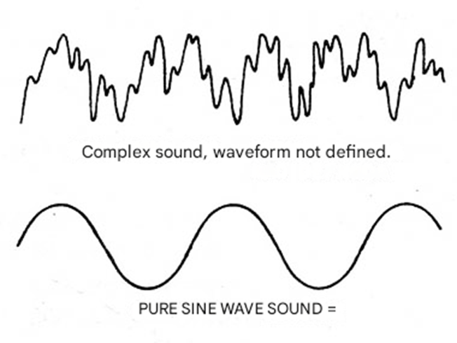
Depending on the instrument or type of voice, the frequency range covered can vary, thus characterizing the different octaves. From one octave to another we have the same notes (or sounds), but with doubled frequencies. If we take any sound, corresponding to a musical instrument or human voice, and simply double its frequency, without significantly altering the waveform, we will have an interesting result: the voice will be "thinner" and the instrument will have a higher pitch, but the content will be the same. Our circuit does just that.
We apply the signal from any source to the input of an amplifier (TBA820).
After amplification, the signal is applied to a bridge of 4 diodes, which constitutes a full-wave rectifier. This rectifier "takes" the already amplified signal and doubles its frequency, as shown in Figure 2.
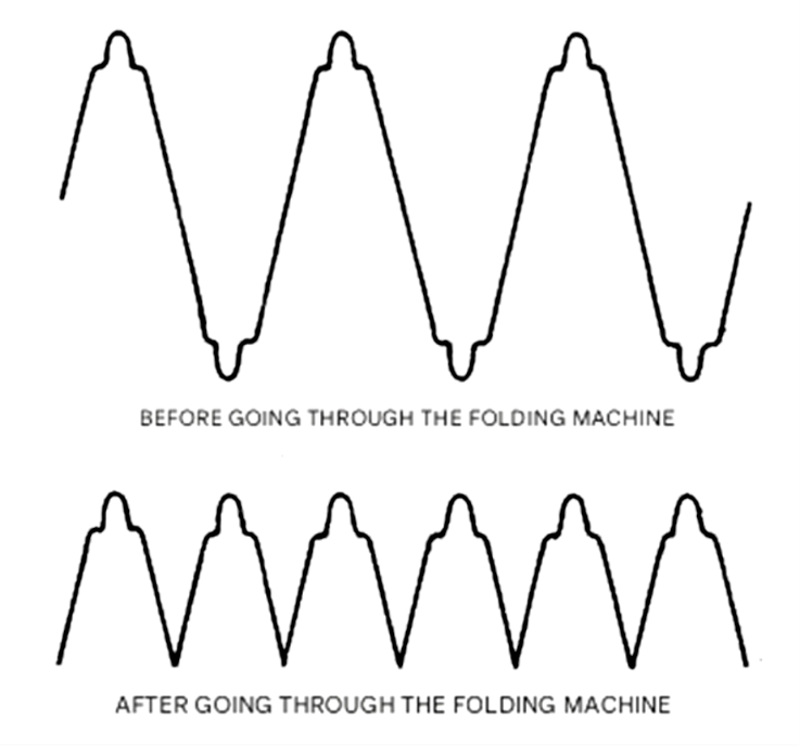
The result is a certain distortion of the signal, with the frequency being multiplied by two, but maintaining the basic contour that characterizes the information. This signal then passes through a tone control that eliminates any unpleasant high frequencies, before being sent to an external amplifier.
Note that we use a transformer because the diodes need a voltage of at least 0.6V to start conducting.
Working with low voltage, at the inflection point of the characteristic curve, as shown in Figure 3, would introduce a very large distortion in the signal.
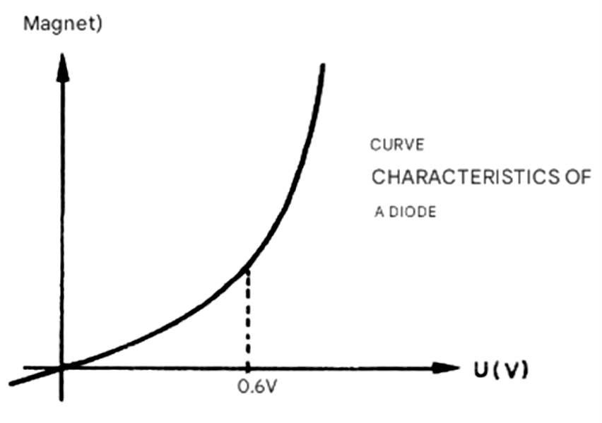
By using an inverted power transformer, we raise the signal voltage to the point where the diodes can work in the linear region of their characteristic, thus obtaining greater fidelity in the contour of the doubled frequency signal. Therefore, the conditions for the device to function satisfactorily are easy to meet: the signal source simply needs to adequately excite the amplifier, to the point where it provides a good power output to the transformer.
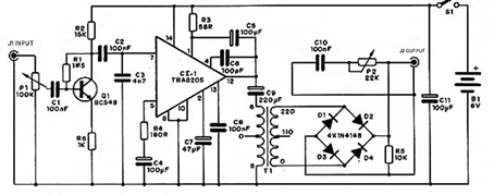
After that, you just need a common amplifier that can be connected to its output, with the power you want in the final sound. Figure 4 shows the complete diagram of this device.
ASSEMBLY
The printed circuit board is shown in Figure 5.
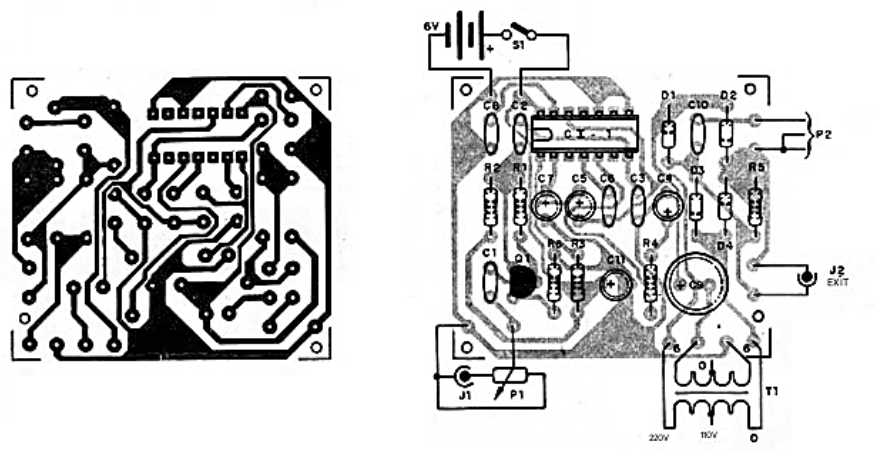
The transformer, for greater economy and ease of project execution, is located outside the board. We can use any transformer with a 110V or 220V primary winding and a single or double 6 to 12V secondary winding with a current between 100 and 500 mA. We especially suggest one with a lower current, as it has smaller dimensions and thus facilitates assembly.
The integrated circuit is mounted in a DIL socket and, as it is a low-power element, providing close to ½ W of output, there is no need for a heatsink. The resistors are all 1/8 or ¼ W with any tolerance. For the electrolytic capacitors, we can use types with a working voltage of 6 V or more. For the others, we can use ceramic, polyester, or styroflex capacitors. The diodes are 1N4148 or any equivalent silicon diode.
Germanium diodes with working voltages of at least 50 V can also be used. Q1 is the preamplifier, which can be a BC548 or any equivalent. Potentiometers P1 and P2 are linear or logarithmic. For the input, we use a jack according to the signal source, suggesting the RCA type, since microphones and phono cartridges have plugs of this type. There is nothing preventing us from connecting an RCA jack in parallel with a common microphone jack.
For the output, we use a shielded cable with a plug according to the auxiliary input (AUX) of the amplifier we are going to use. Normally, we find RCA plugs for this purpose. A common battery holder is used for the batteries. In a fixed application, we suggest using a power supply with very good filtering so that hum does not occur. Placing an H-switch between the input and output allows switching from normal operating mode to double octave mode. Figure 6 shows how to connect this switch.
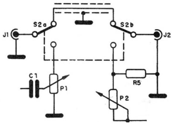
Note that, since this is an assembly that operates with low-intensity audio signals, all precautions regarding hum pickup are important. In particular, note that the signal input cables must be shielded.
TESTING AND USE
To test the unit, connect its output to the input of a common amplifier and a signal source to its input, such as a microphone or even the headphone output of a battery-powered radio or recorder. Adjust P1 and P2 to obtain the desired sound effects on the amplifier, but without excessive distortion or saturation of the final amplifier. Once the operation is verified, simply use the unit. If you want to work with various signal sources, connect a mixer to the octave booster input and work with instruments, microphones, and even background recordings (accompaniment) in a karaoke, for example.
Bill of Materials
IC-1 – TBA820S - integrated amplifier circuit
T1 - transformer with 110 V or 220 V primary and 6 to 12 V x 100 to 500 mA secondary
Q1 - BC548 or equivalent - general-purpose NPN transistor
D1 to D4 - 1N4148 or equivalent silicon diodes
C1, C2, C8 – 100 nF - ceramic or polyester capacitors
C3 - 4n7 - ceramic or polyester capacitor
C4, C11, C5 – 100 uF – electrolytic capacitor
C6 – 100 pF - ceramic capacitor
C7 - 47 uF - electrolytic capacitor
C9 – 220 uF - electrolytic capacitor
R1 - 1M5 - resistor (brown, green, green)
R2 – 15 kΩ - resistor (brown, green, orange)
R3 - 56 ohms - Resistor (green, blue, black)
R4 - 180 ohms - Resistor (brown, gray, brown)
R5 – 10 kΩ - Resistor (brown, black, orange)
R6 – 1 kΩ - Resistor (brown, black, red)
P1 – 100 kΩ – Potentiometer
P2 – 22 kΩ or 47 kΩ - Potentiometer
S1 - Simple switch
B1 – 6 V - 4 small batteries
Miscellaneous: printed circuit board, mounting box, battery holder, knobs for the potentiometers, shielded wires, screws, nuts, wires, plug, jack, etc.
Note: In case of distortion or lack of excitation, R2 can be changed, which will be in the range of 470 ohms to 47 kΩ. Experiment if you have difficulties matching the characteristics of your signal source with the input of this circuit.


