
ART311S ART2228
Products on a conveyor belt or people passing through a location can be counted electronically with the help of a circuit like the one we describe. Each interruption of the two light beams, which must occur in a specific direction, generates single pulses that can trigger a digital either electronic or electromechanical counter. The circuit uses common LDRs as sensors, which guarantees excellent sensitivity. In this way, small lamps of 5 watts or less can be used to form the beam or even, depending on the installation method, ambient light.
Note: the article is from 1990; in a more modern version, we can use high-brightness LEDs as a light source.
The input circuit has two adjustments that operate over a wide range of brightness and can also be powered with voltages in the range of 5 to 12 volts, making it compatible with both TTL and CMOS technologies. The 4093 integrated circuit used as the basis for this project is quite common and has a very low cost.
HOW IT WORKS
Two of the four non-AND (NAND) trigger gates of a 4093 integrated circuit form a Set-Reset type flip-flop.
Voltage divider circuits are connected to the Set and Reset inputs, in which one branch has photo resistors (LDRs) and the other has biasing and adjustment devices, formed by resistors and trimpots. With both LDRs illuminated, the levels at the flip-flop inputs are kept high, but actuating the reset switch causes a shortly low level at input 1 to bring output 3 to a low level, and this level is maintained by the circuit's feedback effect.
When an object shortly interrupts the light on LDR1, this is equivalent to shortly bringing input 6 to a low level, which switches the flip-flop with a change in the state of its output. When the object cuts the beam of light illuminating LDR2, the circuit is reset.
The third gate Cl1c of the integrated circuit is used as a buffer, isolating the flip-flop output from the excited load, but at the same time inverting the signal levels. For a further inversion, we can use the fourth gate (Cl1d).
The trimpots P1 and P2 are used to adjust the exact points at which the flip-flop is triggered, depending on the illumination of the LDRs. For perfect operation, the LDRs must be mounted in opaque tubes with converging lenses, to receive light only from the corresponding source. The width of the pulse produced, which is important in certain applications, depends on the speed at which the object passes in front of the two LDRs and their separation. This should be studied according to each application in mind.
ASSEMBLY
What we have is a basic circuit that should be part of a more elaborate project that includes the counting stages. Figure 1 shows the complete system diagram.
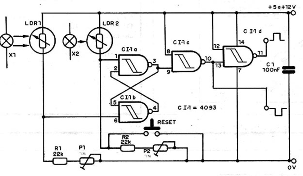
C2 is ceramic and the resistors are 1/8 W. The trimpots are common and the LDRs are common round ones. The wires connecting to the LDRs should not be longer than 5 meters to avoid the production of bounce or pickup of hum that leads to erratic operation of the triggers. The lamps can be low voltage or even powered by the local network, depending on the light intensity required for the application.
Note: The article is from 1990. In a modern version, we can use high-brightness LEDs as a light source. The Reset switch is a common push-button switch.
TESTING AND USE
For a bench test, an LED can be connected in series with a 1 kΩ resistor to one of the outputs. Then simply adjust the trimpots so that when the shadow passes (in the order indicated in the explanations), the flip-flop switches twice, with the set and reset activated. Once the operation is verified, simply install or implement the complete counter project.
MATERIAL LIST
IC-1 - 4093 - CMOS integrated circuit
LDR1, LDR2 - common LDRs
P1, P2 - 1 MΩ - trimpots
R1, R2 - 22 kΩ x 1/8 W - resistors (red, red, orange)
C1 - 100 nF - ceramic capacitor
Miscellaneous: printed circuit board, socket for the integrated circuit, wires, solder, etc.


