
ART3315S ART2859
In addition to energy and data, a transmission line can carry much more than the energy and information we need. Thus, undesirably, surges, transients, and other disturbances can arrive, capable of affecting not only the quality of the energy and the integrity of the data but also causing serious damage to connected equipment.
Neither the energy that arrives through a transmission line nor the data that comes through the cables are pure, nor completely free from disturbances or distortions. In our articles, we have addressed several times the problems that arise from the quality of energy and the means to prevent them from appearing, or if they appear, how to solve them.
Industrial equipment that uses data transmitted via cables and is powered by the local power grid is sensitive to a number of disturbances that need to be avoided. Improper operation, frequent circuit burnouts, or even accidents can be caused by problems that are not generated within the equipment itself but come from outside in the form of voltage spikes, surges, and transients.
One of the main sources of disturbances affecting the transmission of power and data through cables exposed to the environment is the result of atmospheric discharges. A lightning strike, even if it occurs a considerable distance from the location where a power or data transmission line passes, can induce short-duration voltage spikes, but with very high values. When lightning strikes, even if it passes through a lightning rod, as shown in the Figure.1, a current field is created, inducing voltages whose value depends precisely on the gradient of this field
.
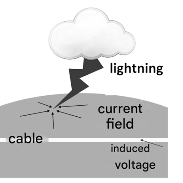
A cable passing through this current field can be subjected to an extremely intense induction process, capable of producing dangerous spikes that propagate to devices connected at its ends. It has been observed that the effects of a lightning strike can affect electronic equipment at a distance of up to 3 km.
Obviously, a direct strike on the cable or on a pole that secures that cable is even more dangerous. Sparks jump easily between metallic structures and cables or between cables, as illustrated in Figure 2, also creating a situation of induction of dangerous high-voltage pulses, which propagate to the equipment connected to these cables.
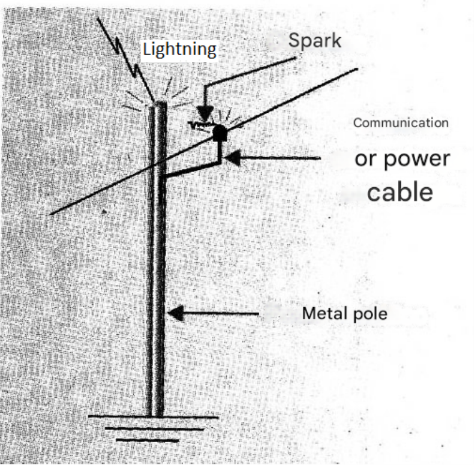
The voltage spikes that appear at the ends of the cables and are therefore applied to the equipment can reach thousands of volts with enough energy to cause the complete burnout of all its circuits. It is also important to note that voltage spikes, generated by atmospheric discharges, do not only occur during a thunderstorm with lightning.
The presence of charges in the atmosphere is constant, and discharges can occur even on cloudless days. Sparking due to charges accumulated in the air, with less intensity, can perfectly well arise generating transients in the same way, capable of causing damage to equipment, see Figure 3.
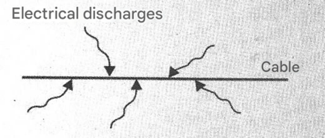
To protect equipment against these transient spikes, which can reach high values, there are several techniques.
PROTECTION SYSTEMS
The basic idea of a protection system is to divert the high-voltage peak propagating through the power or data transmission line to ground before it reaches sensitive equipment. This system is called a "shunt" and is the most common. Therefore, to protect the power line, we connect the device in parallel with it at the equipment input, as shown in Figure 4.
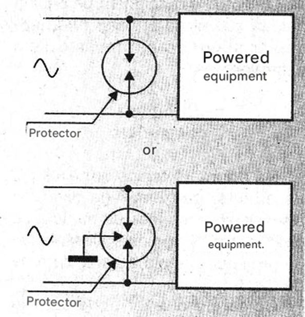
For a data transmission line, such as a telephone line, we connect the device in parallel before it enters the equipment. See Figure 5.
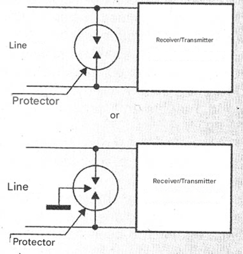
Grounding is very important, although in some cases the return wire of the line itself is used, connected to ground. The device used is usually some type of component that has a very low electrical resistance to the transient, but which is seen as an open circuit for the signal or energy that must reach the equipment. Several devices are used for this purpose.
Varistors
Zinc oxide varistors (SlOVs, MOVs, etc.) are components that have a characteristic curve similar to that shown in Figure 6.
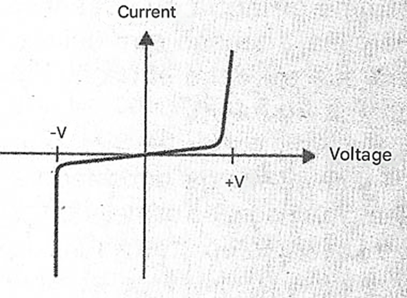
For normal circuit voltages, which correspond to the signals or energy being transmitted, they have a very high resistance, not affecting the circuit. However, for voltages above a certain value (which is the nominal voltage of the device), they switch, exhibiting a very low resistance. As illustrated in Figure 7, where we have the granular structure of such a device, a spark occurs through the device diverting the energy of the transient pulse. In this energy diversion, we have two important factors to consider.
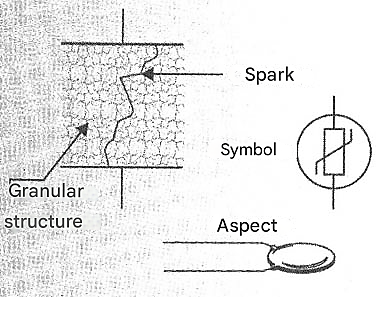
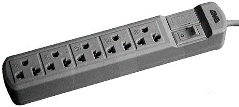
Firstly, the device must be able to absorb the energy of the spark, which, in the most serious cases, such as a lightning strike near the cable itself, can exceed its capacity, causing its destruction. The second point is that the effects of sparking through the device are cumulative, meaning that with each absorbed pulse, the spark "wears down" the device a little, burning granules of its structure and, over time, it may stop working. Varistors are widely used in computer-protected outlets, but they are suitable for any type of household or even industrial equipment that is sensitive to surges propagating through the power grid. Figure 8 shows an example of these outlets.
Obviously, for industrial machines and other sensitive equipment, the varistor can be added internally to the circuit's power input.
Spark gaps (Arrestors)
Spark gaps are protective devices that rely on the dielectric strength of ambient air. Air is an insulator up to a certain point. If the voltage exceeds a certain value, the air loses its insulating properties, ionizes, and begins to conduct electric current intensely. This is what happens with atmospheric discharge itself, when the moisture from the rain, at the moment it forms, reduces the dielectric strength of the air to the point of allowing discharges to occur between clouds and between clouds and the ground in the form of lightning.
For dry air, the dielectric strength of the air is approximately 10,000 V/cm, for flat electrodes. This means that two metal plates separated by a distance of 1 cm, as seen in Figure 9, can insulate a voltage of up to 10,000 V.
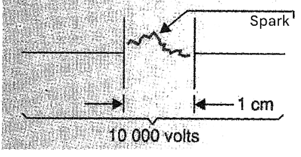
A higher voltage "breaks" the dielectric, which is the air, and a spark appears. For electrodes in the form of a point, the distance decreases, and that's where the spark gap comes in, used to protect telephone and data lines in many devices, including regular telephones. This component consists of two points or needles separated by a distance that depends on the voltage we want it to activate. See Figure 10.
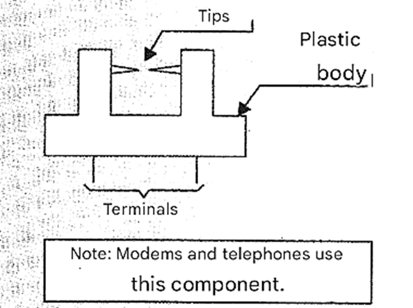
If a voltage spike, caused by an atmospheric discharge, for example, reaches the spark gap, ionization of the air between its points occurs, and a spark arises, absorbing the energy and preventing it from reaching the device.
Gas spark gaps
Electrodes are placed inside a bulb filled with gas. The type of gas basically determines the ionization voltage, and therefore, the conduction point. When the conduction voltage is reached, the gas ionizes and exhibits very low resistance. Under these conditions, the high-voltage pulse present in the protected line is diverted to ground. The type of gas also determines how much energy the protector can absorb without being destroyed.
Commercial Circuits
Figure 11 shows an example of a protector that employs several different devices to obtain clean power to supply equipment from the 220 V mains.
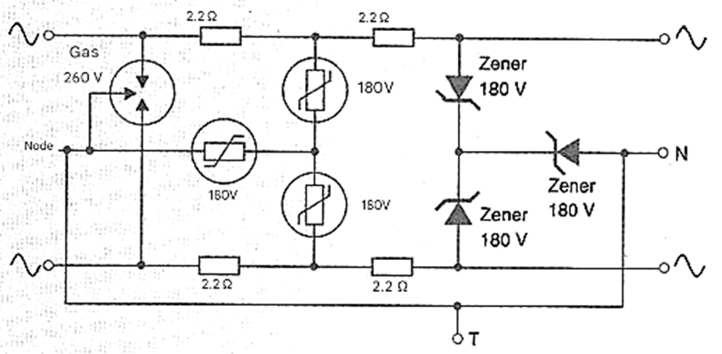
As the reader can see, at the input we have a double gas protector for a voltage of 260 V. This device conducts to ground any voltage pulse or transient whose peak value exceeds 260 V. Next, we have 3 zinc oxide varistors of 180 V that act if the voltage peak is at an intermediate value between the peak of the power grid (approximately 155 V) and 260 V.
Finally, we have 3 180 V zener diodes that provide the final protection for the powered equipment. The low-value resistors in series with the circuit do not cause appreciable voltage losses and at the same time serve as fuses, that is, they open the circuit if a short circuit occurs, whether due to problems in the protection or due to problems in the protected equipment itself that have other causes.


