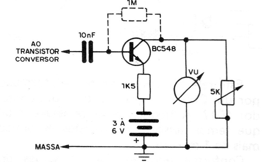
It is a small circuit, which coupled to any medium or short-wave radio, allows to evaluate the 'intensity of the RF signal that "enters" it. The assembler will be able to use it to be able to better tune the stations, mainly shortwave, according to the highest signal intensity verified. The circuit, shown in the figure, consists of a NPN transistor for general use, polarized in the common emitter configuration, with a low-value polyester capacitor connected to its base, to allow high frequencies to pass. The value of this capacitor can be changed to obtain a convenient circuit response, according to the characteristics of the transistor itself. One of the points in the circuit is connected to the radio ground, and the other is connected to the converter transistor, the assembler being responsible for selecting the terminal of the latter that best provides greater signal strength. The 1M resistor, connected between the collector and the base, may be necessary in some cases. The VU used is of the type found in recorders, however anyone can be experienced, just adjusting the sensitivity in the trimpot and, therefore, the ideal point of operation.


