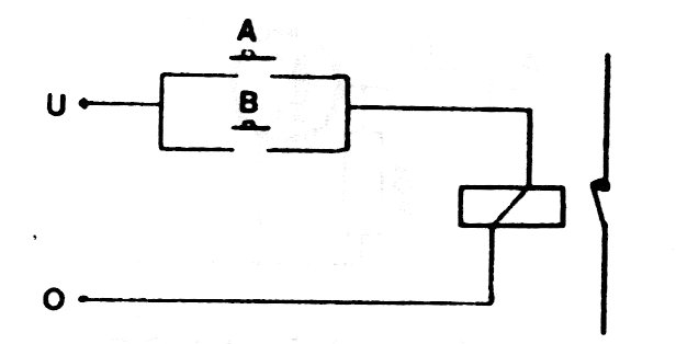
In this case, the output will be activated (1) when both inputs are deactivated, that is, neither one nor the other. The circuit is implemented with a relay, as shown in the figure. Note that we make use of the NC and C contacts.
The truth table will be as follows:
A B O
0 0 1
0 1 0
1 0 0
1 1 1