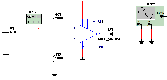
This simulation shows how to use an operational amplifier as a voltage comparator. The sample uses the 741 but it can be replaced with any other suitable op. amp. The power supply is simple (one voltage) and in the simulation a sinusoidal signal is applied to the input. The circuit for the simulation is shown in the figure 1.

Trigger voltage is given by:
Vd = Vcc(R2/(R1+R2)) onde
Where:
Vd is the trigger voltage
Vcc is the supply voltage
R1 and R2 are the resistors;
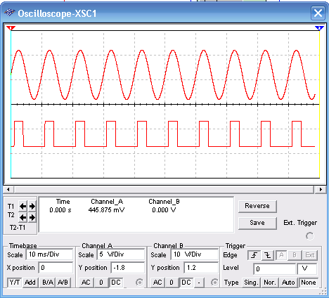
Wave shapes in the circuit as displayed in the virtual oscilloscope of the Multisim are shown in figure 2.

Download the simulation files and Netlist - click here (msb0069.zip)


