
ART3928S ART5563
Note: Article published in the magazine Eletrônica Total, issue 159, 2014.
The idea behind this project is simple: the power grid of a home or other type of installation is used to send the sensor signals, when they are triggered, to a central station placed in a strategic location. Each sensor has its own transmitter and can be moved at will, if there is an outlet nearby for us to connect to it.
Even a neighbor's house can be protected, and if you are traveling, this central unit can easily be transported to the house next door. When the alarm goes off, it will alert someone who can then take action. The number of sensors used is virtually unlimited, and additional features for protection in the event of a power outage can be added.
The circuit is very simple and requires no complicated adjustments, especially frequency adjustments, since it doesn't operate with tuned filters. The use of a dedicated circuit prevents short-duration transients, such as those that occur when switching on switches and appliances, from triggering the alarm erratically.
The alarm's action is timed, and for short intervals, it can even operate as a remote control.
Features
• Power supply voltage: 110/220 V AC
• Operating frequency: 40 kHz (approximately)
• Timing: 10 seconds to 10 minutes
• Control capacity: 2 A
• Sensor types: switches, optical, wires, thermal
• Number of sensors: unlimited
How it works
Figure 1 shows the block diagram of the transmitter, which is where we begin our analysis.
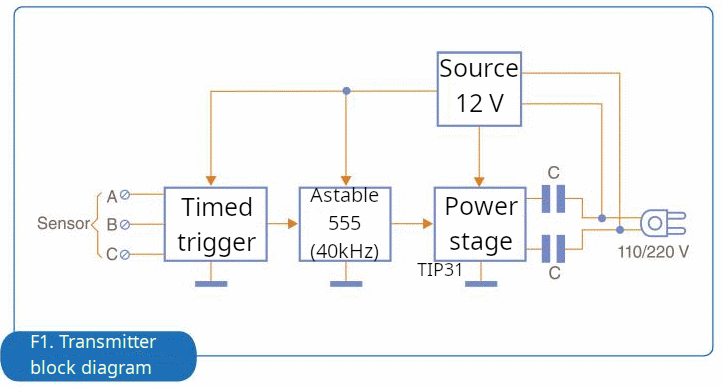
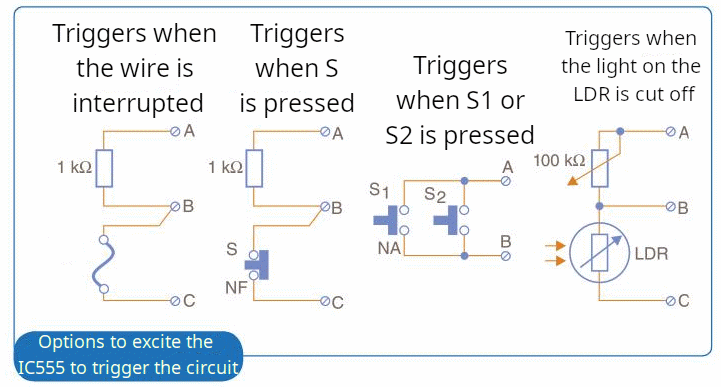
The trigger circuit is based on a 555 integrated circuit (CI-1) connected in a monostable configuration, in which the time the output level remains high is determined by C6 and the setting of P1. Capacitor C6 can have values ranging from 10 pF to 1000 µF, in which case the alarm may sound for more than half an hour. The 555 is triggered by the momentary application of a low level to pin 2, which is achieved by transistor Q1 and a capacitor (C5).
There are therefore several possibilities for exciting the 555 to trigger the circuit, some of which are shown in Figure 2. Figure 2a uses wire sensors that, when interrupted, cause Q1 to switch, thus triggering the 555. Figure 2b shows triggering using reed switches or NC micro switches, while Figure 2c shows triggering using NO switches. To use an LDR, we have the connection shown in figure 2d. Note that, in this case, the momentary passage of a person that cuts the light incident on the LDR causes it to trigger.
The timing circuit serves to activate an oscillator with another 555 in the astable configuration (CI-2). This circuit operates at a frequency of approximately 40 kHz, provided by resistors R6 and R7 and capacitor C7.
The signal from this oscillator is fed to a power stage consisting of a TIP31 transistor capable of producing an output of a few hundred miliwatts, which is applied directly to the local grid via capacitor C2. This capacitor, like C1, is an important element of the transmitter, as it must present a low impedance to the signal, coupling it directly to the grid. We recommend using polyester capacitors with a working voltage of at least 400 V for a 110 V grid and at least 600 V for a 220 V grid.
The transmitter has a protection fuse at its input and its power supply is stabilized, having at its base an integrated 7812, which must be equipped with a heat radiator.
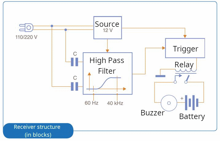
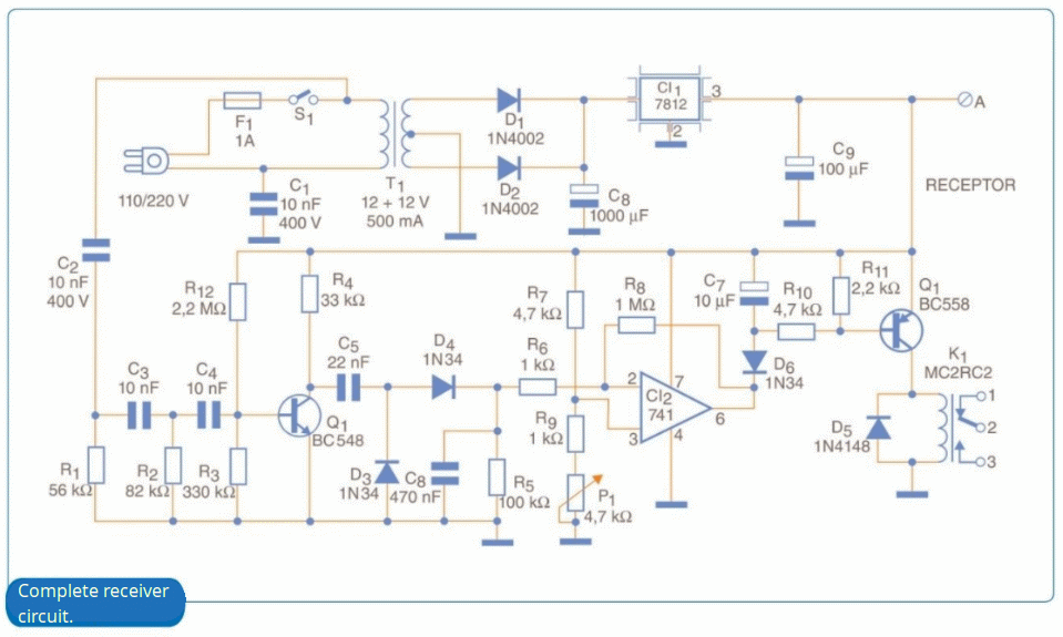
The receiver has the structure shown in Figure 3. The signal captured from the power supply via capacitor C2, which must also have a high isolation voltage, is fed to a high-pass filter formed by C3/C4/R1/R2 and R3. This filter eliminates the 60 Hz component of the local power supply, leaving only the signal that may be present from the transmitter.
After amplification, the signal is detected and then amplified by a 741 operator, which does not require a symmetrical source in this case. D3 and D4 form the detector, which then applies a positive voltage to the inverting input of the operator, the value of which depends on the strength of the captured signal.
P1 sets the reference voltage at the non-inverting input. Thus, in the absence of a signal, we adjust P1 so that the reference voltage is approximately half the supply voltage, or slightly less, so that the output has a positive voltage, but very close to the transition to zero volts (Figure 4).
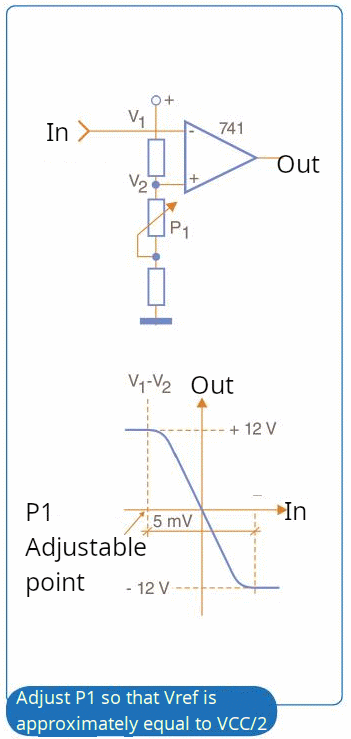
When there is an input signal, a positive voltage appears and is strongly amplified, bringing the operational output very close to zero. This causes D9 to be forward-biased and Q2 to be biased.
The assembly has a certain inertia that prevents operation with transients. Therefore, the signal must be present for a certain period for the voltage at the output of D4 to charge C6, triggering the operational relay. Likewise, when the signal disappears, the relay trips in an instant, as C7 remains. This same capacitor prevents contact vibration during relay activation.
D5 protects the transistor against the high voltages generated in the relay coil during switching. The relay activation time depends on the transmitter. Therefore, depending on the timing of each sensor, the relay activation time will vary.
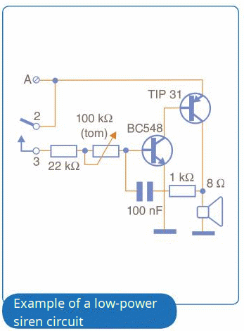
The circuit is powered by a stabilized power supply based on the 7812 integrated circuit, which must be equipped with a small heat sink. Figure 5 shows the circuit of a low-power siren that can be powered by this circuit.
Assembly
We begin by showing the complete transmitter circuit in Figure 6.
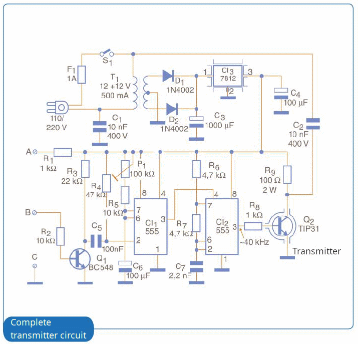
Figure 7 shows the printed circuit board for assembling the transmitter.
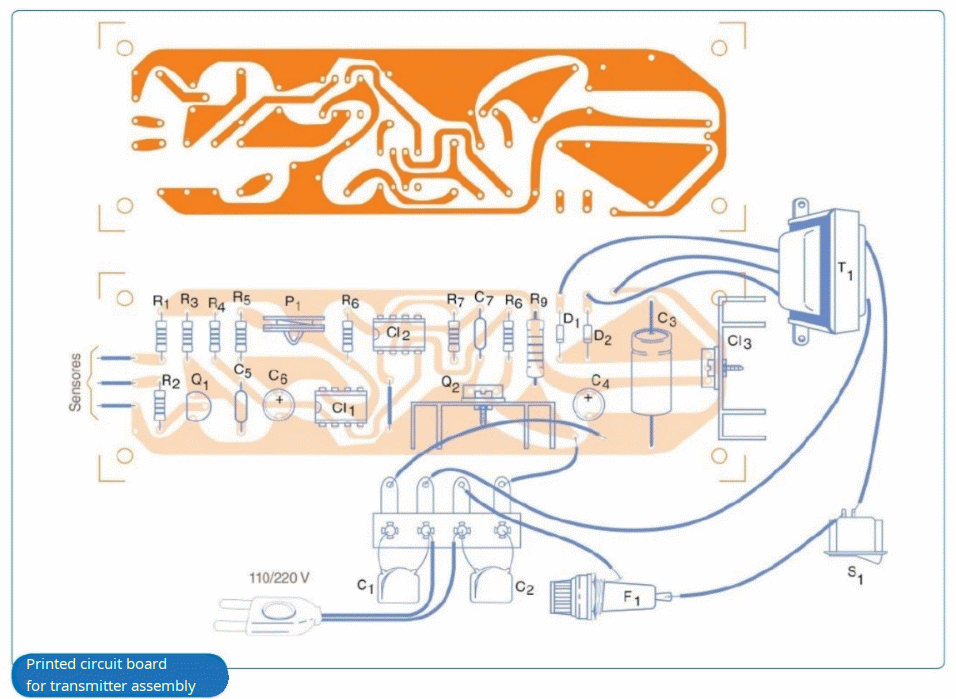
The "board + external elements" assembly can be installed in a plastic box located near the protected area and connected to the nearest power outlet. Figure 8 shows the complete receiver circuit.
The printed circuit board is illustrated in Figure 9.
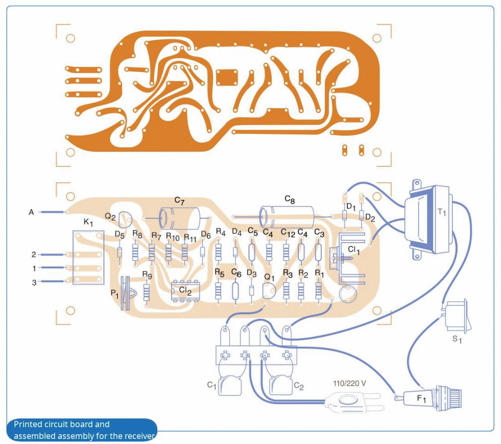
The components of both the transmitter and receiver are not critical. The resistors are all 1/8 or 1/4 W with a 5% or 10% tolerance, except for R9 in the transmitter, which must be 2 W. Transistor Q2 (in the transmitter), as well as the 7812 integrated circuits in both the transmitter and receiver, must be equipped with heat sinks.
Capacitors less than 1 µF can be polyester or ceramic. Special attention should be paid to capacitors C1 and C2 in the transmitter and receiver, which have high isolation voltage. The electrolytic capacitors are rated for 16 V, except for C3 on the transmitter and C8 on the receiver, which are rated for 25 V.
For D3, D4, and D6, any germanium diode can be used, and for the power supply rectifiers, higher-voltage equivalents of the 1 N4002 can be used. The 555 and 741 integrated circuits can be mounted in DIL sockets, and the receiver transistors Q and Q2 accept equivalents.
Transformers must have a primary winding that matches the local grid, and the minimum secondary current is 500 mA. Any standard LDR will work for the light sensor, and the receiver uses a 12 V MC2RC2 relay from Metaltex, which can also be mounted in a DIL socket, making it easy to replace if necessary. Equivalent relays can be used, but require a new PCB design.
Testing and Use
Before closing the units in their cases, it is a good idea to perform a bench test. Using a multimeter and an LED in series with a 1kohm resistor connected to the relay contacts will greatly help monitor operation and make adjustments. Connect both units to the power supply, measuring the voltages on pin 3 of the 7812 integrated circuits. 12 V should be present.
Set P1 on the transmitter to the minimum resistance position. Then, adjust P1 on the receiver until the relay deactivates, which will cause the LED to turn off. Take a short piece of wire and touch its ends to points A and B on the transmitter, activating transistor Q1 and triggering the unit. The relay should engage immediately, and the LED should illuminate for a few seconds. If this does not work, re-adjust P1 on the receiver and try again.
Note that there should be a P1 set point where the LED transitions from off to on, and the ideal setting occurs as close as possible to this transition. If this does not happen, check that D6 is not inverted, or that there aren't problems with CI-2 or Q2, or check for D5 inversion (which can cause Q2 to burn out).
You can check the receiver's operation by disconnecting C2 and applying a 40 kHz signal from a function generator or audio generator to C3, which should activate the relay. To check the receiver's operation, connect a frequency counter to pin 3 of C1-2. A 40 kHz signal should be observed when A and B are briefly short-circuited.
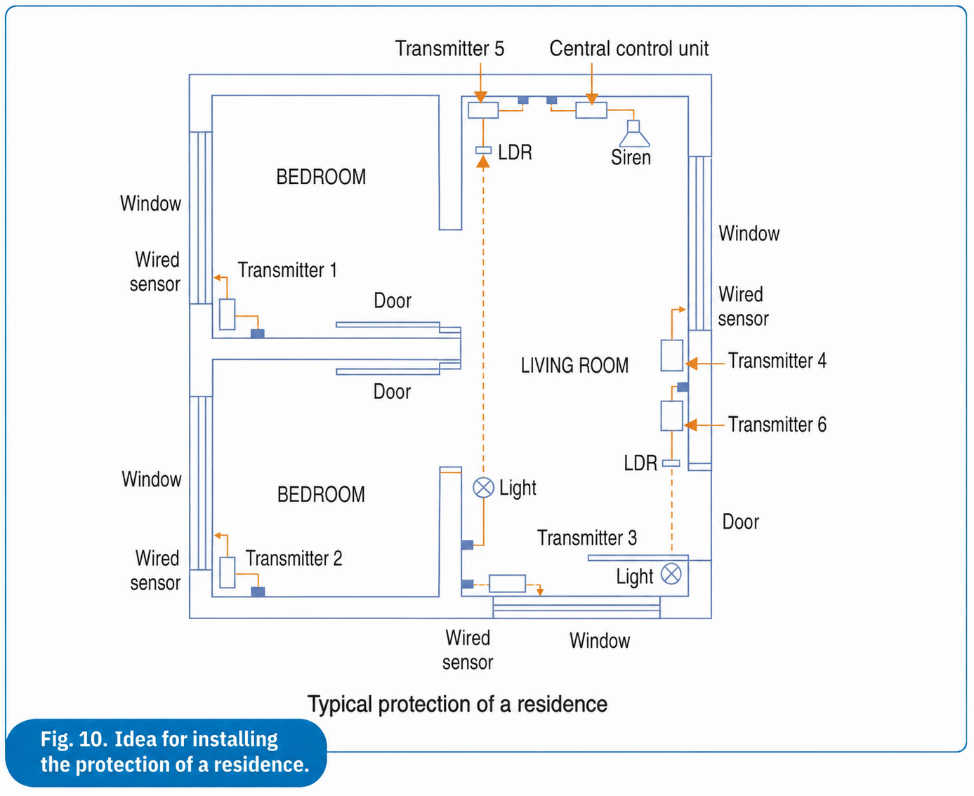
CI-1 triggers by connecting a multimeter to the DC voltage scale on pin 3. A transition from 0 V to approximately 12 V occurs. Once the function is confirmed, it is time to consider installation. In figure 10 we indicate how this can be done using different sensors.
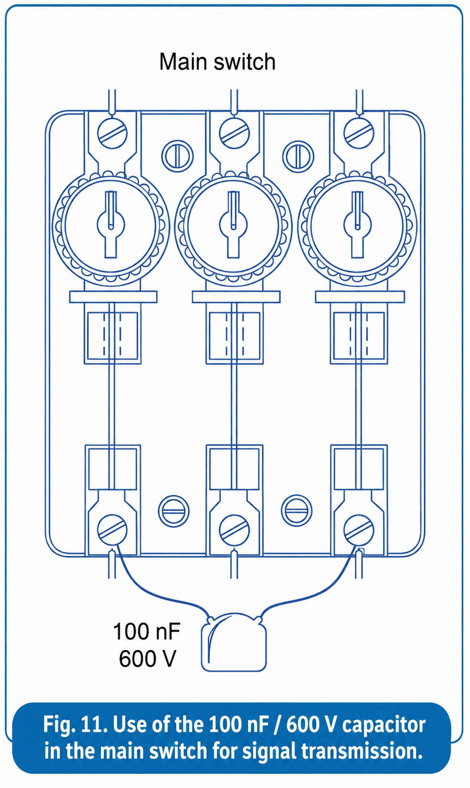
Note that a home may have two phases, making it difficult for the signal to pass from one to the other. This means that there may be outlets in your home that do not work properly. We can facilitate signal transmission by using a 100 nF x 600 V capacitor connected to the main switch, as shown in Figure 11.
This feature may also be necessary if the signal has difficulty reaching the sensor when placed in a neighbor's house.
List of Materials
Transmitter:
CI1, CI2 - μA555 - timer integrated circuit
CI-3 - μA7812 - 12 V voltage regulator integrated circuit
Q1 - BC548 - general-purpose NPN transistor
Q2 -TIP31 power NPN transistor
D1, D2- 1N4002 - silicon rectifier diodes
F1 = 1A fuse
S1 - single-ended switch
P1 - 100 Kohms, trimpot
T1 - transformer with local grid primary and 12+12 V x 500 mA secondary
C1, C2 - 10 nF x 400 V - polyester capacitors
C3 - 1000 μF x 25 V - electrolytic capacitor
C4 - 100 μF x 16 V - electrolytic capacitor
C5 - 100 nF polyester or ceramic capacitor
C6 - 100 μF x 16 V - electrolytic capacitor
C7 - 2,2 nF polyester or ceramic capacitor
R1, R8 - 1 kohm - resistors (brown, black, red)
R2, R5 - 10 kohms - resistors (brown, black, orange)
R3 - 22 kohms - resistors (red, red, orange)
R4 - 47 kohms - resistors (yellow, violet, orange)
R6, R7 - 4.7 kohms - resistors (yellow, violet, red)
R9 -100 ohms x 2 W - resistor (brown, black, brown)
Mounting box, power cable, heat sinks, fuse holder, wires, sensors, solder, etc.
Receiver:
CI-1 - μA7812 - voltage regulator integrated circuit
CI-2 - μA741 - operational amplifier
Q1 - BC548 - general-purpose NPN transistor
Q2 - BC558 - general-purpose PNP transistor
D1, D2 - 1N4002 or equivalent - rectifier diodes
D3, D4, D6 - 1N34 or 1N60 - germanium diode
D5 - 1N4148 - general-purpose silicon diode
K1 - MC2RC2 - Metaltex micro relay for 12 V
P1 - 4.7 kΩ - trimpot
F1 - 1 A - μF fuse
S1 - simple switch
T1 - transformer with primary according to the local network and secondary of 12 + 12 V x 500 mA
C1, C2 - 10 nF x 400 V - polyester capacitors
C3, C4 - 10 nF - polyester capacitors
C5 - 22 nF - polyester or ceramic capacitor
C6 - 470 nF - polyester capacitor or ceramic
C7 - 10 µF - electrolytic capacitor
C8 - 1000 μF x 25 V - electrolytic capacitor
C9 100 μF x 16 V - electrolytic capacitor
R1 - 56 kohms - resistor (gray, blue, orange)
R2 - 82 kohms - resistor (gray, red, orange)
R3 -330 kohms - resistor (orange, orange, orange)
R4 - 33 kohms - resistor (orange, orange, orange)
R5 - 100 kohms - resistor (brown, black, yellow)
R6, R9 - 1 kohms - resistors (brown, black, red)
R7, R10 - 4.7 kΩ - resistors (yellow, violet, red)
R8 -1 mohms - resistor (brown, black, green)
R11 - 2.2 kohms - resistor (red, red, red)
R12 - 2.2 mohms resistor (red, red, green)
Miscellaneous
Power cable, printed circuit board, wires, fuse holders, heat sinks, integrated circuit sockets, solder, etc.


