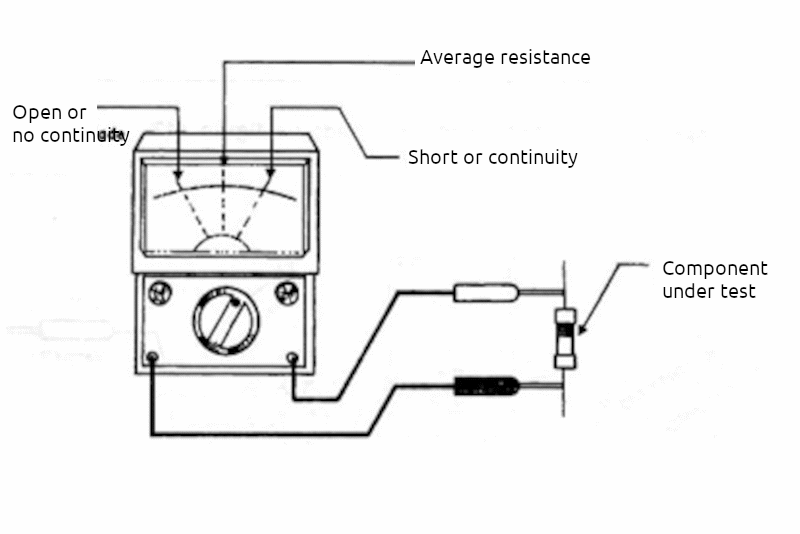
With the simple instrument that we will describe, continuity and resistance measurements, which are very useful in component testing, can be performed. Thus, resistance measurements of up to 50,000 ohms can be performed with good precision if the scale is previously calibrated based on resistors of known values. For general tests, we have the following type of operation: When the instrument's test leads are placed against the component being tested, we have the following reading possibilities, as shown in figure 1.

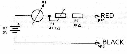
When the needle remains completely to the left of the scale or does not move at all, we have an open circuit or high resistance condition. In this case, we can say that the circuit is open, or that no current flows through the circuit or that its resistance is such that very little current flows. The technical term for this condition is "lack of continuity". When the needle remains in the central range of the instrument's scale, it is a sign that the circuit or component being tested has a resistance in the range of 5,000 to 50,000 ohms and, therefore, has average continuity. When the needle remains completely to the right, or in the range close to the limit on the right, we have a low resistance condition. With the needle completely to the right, we actually have a "short circuit" condition, when the current in the circuit or component being tested can become very high. The instrument used in the tester is a microammeter with approximately 200 uA full scale and is powered by two common batteries. The only adjustment is made by touching one test lead to the other and moving the trimpot to the position where the instrument has the needle going all the way to the right (indicate the maximum). In figure 2 we have the complete diagram of the tester that can be assembled in a plastic box the size of a soap dish.

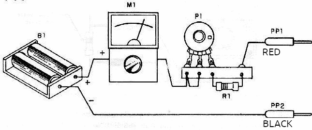
The actual appearance of the assembly is shown in Figure 3.
There is no need to use a printed circuit board given the reduced number of components used. Any microammeter with a full scale of 100 uA to 400 uA can be used. Observe the polarity of the instrument when turning it on, because if it is reversed the needle tends to move in the opposite direction to what is expected. To use, simply touch the test leads to the component or circuit under test and observe the needle of the instrument. Never use the tester on circuits that are working. The power supply to the circuits under test must be turned off and, in the case of components; they must be disconnected from the circuits in which they are used.
MATERIAL LIST
M1 - 0-200 uA - microammeter
P1 - 47k ohms - trimpot
B1 - 3V - 2 small batteries
R1 - 1k ohms - resistor - 1/8W
PP1, PP2 - test leads, black and red
Miscellaneous:
Box for the device, two battery holders, wires, solder, etc.


