
ART5479 ART3920S
Note: Article published in Eletrônica Total 142 of 2010.
In a rhythmic light system, we have circuits that control regular lamps based on signals from audio amplifiers. These signals cause the lamps to flash in sync with the sounds, thus producing a very interesting effect, used in musical groups, theaters, concert halls, and many other cases.
The project discussed here is relatively simple, allowing the reader to assemble and use it even at parties in their home. In our system, as illustrated in Figure 1, we use three filters that separate the control signals into three different channels.
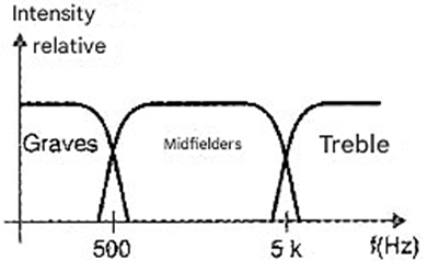
One channel uses bass sounds to control a set of lights of one color (for example, red). The other channel uses mid-range sounds to control lamps of another color (for example, yellow), while the third channel uses treble sounds to control a set of lamps, for example, blue.
The result of this circuit's operation is a very interesting light effect, with variations in color and brightness according to the music or sound being played in the environment. If the reader needs this type of equipment, here is the opportunity to make their own assembly.
How it Works
Figure 2 shows the block diagram representing the 3-channel rhythmic light system. As we can see, the audio signals that will control the circuit are taken from the speaker output to the sound amplifier.
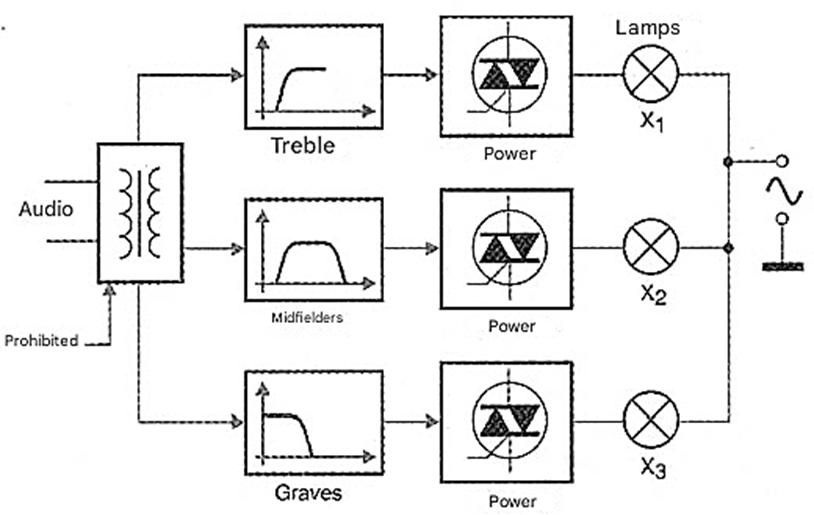
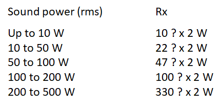
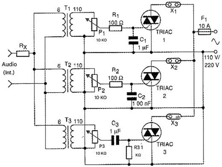
These signals pass through a limiting resistor (Rx) whose purpose is to limit the power applied to the circuit, depending on the power of the amplifier being used. Table 1 below provides typical values for this resistor according to the power of the sound used. To isolate the amplifier circuit from the rhythmic light circuit, which is powered by the mains, we use three transformers, one for each channel.
These transformers also serve to match the low output impedance of the sound system with the high impedance of the trigger input of the semiconductor devices used to control the lamps. In the high-impedance winding of each transformer, we have a sensitivity adjustment potentiometer for the corresponding channel.
Next are the filters that are calculated to allow certain frequency ranges to pass, see Figure 3.
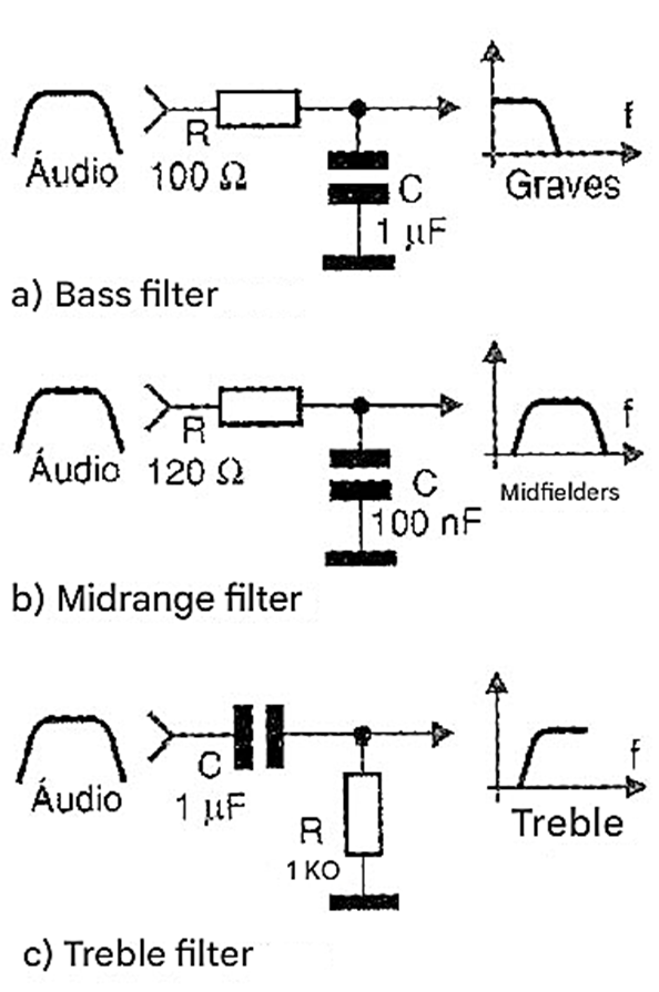
Since highly selective circuits are not required, the ranges determined by the filters are approximate, allowing the reader to make changes to the values of the components used. The output of each filter is connected to the gate of TRIACs, capable of controlling a fairly high current. TIC226 suffix B was used for the 110 V network or suffix D for the 220 V network. A protective fuse completes the circuit, this component being interposed between the TRIACs and the power network.
Assembly
Figure 4 shows the complete diagram of the rhythmic light system.
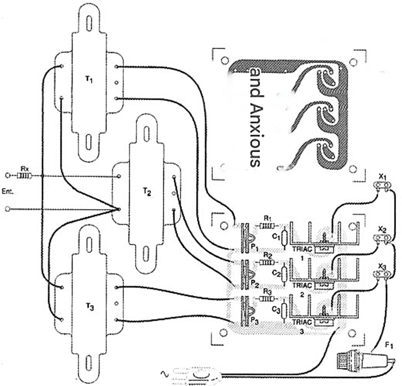
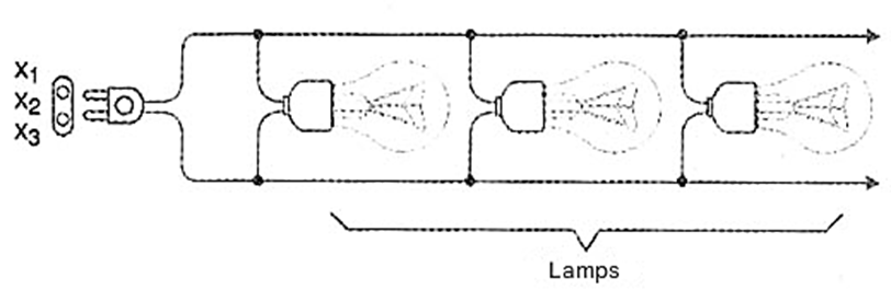
A printed circuit board for the smaller components is suggested in figure 5. Note that the high-current traces coming from the main terminals (MT, and MT) of the TRIACs should be quite wide in view of the current intensity they must control. The TRIACs should be mounted on good heat sinks, especially if the circuit is to operate at the limit of its capacity, i.e., with a good number of lamps. Common sockets were used for the lamps, where sets of lamps of different colors will be connected in parallel, as shown in Figure 6.
Connecting wire to these lamps can be long so that they are well distributed throughout the environment in which they should operate. Special care must be taken with the insulation, as this circuit is directly connected to the power grid. The transformers are of the common type used in power supplies with a primary winding of 110 V or 220 V, and a secondary with any voltage between 6 and 12 V and current in the range of 300 to 500 mA.
Potentiometers exist precisely to adapt the characteristics of these components to the circuit, in order to make the adjustment for optimal operation. The entire assembly can be installed in a wooden or plastic box with good ventilation for the TRIACs.
Testing and Use
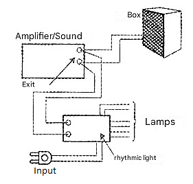
To test the device, and to use it, connect its input to the speaker output of any channel of a sound system, see example in figure 7. Turn on the sound system, playing music at medium volume. Initially, connect a 15 to 60 W lamp of any color to the output of the rhythmic light system, one on each channel. Then adjust each of the potentiometers so that the lamp corresponding to each channel flashes with the bass, mid-range or treble sounds.
If you want to change the frequency response of the circuit, depending on the tolerances and specific characteristics of the components used, modify capacitors C1, C2, and C3.
Then, to use the device, simply adjust the potentiometers according to the volume of the sound system with which it is used.

TRIAC1, TRIAC2, TRIAC3 - TIC226B
(110V) or TIC226D (220V) - Common TRIACs
T1, T2, T3 - Transformers - see text
P1, P2, P3 - 10 kΩ - linear or logarithmic potentiometers
Rx - Resistor according to sound power - see text
X1, X2, X3 - Common sockets
F1 - 10 A - fuse
R1 - 100 Ω x 1 W - resistor - brown, black, brown
R2 - 120 Ω x 1 W - resistor - brown, red, brown
R3 - 1 kΩ x 1/8 W - resistor - brown, black, red
C1, C3 - 1 µF x 200 V - polyester capacitor
C2 - 100 nF - ceramic or polyester capacitor
Miscellaneous:
Printed circuit board, Heat sinks for the TRIACs, high current power cable (10 A), knobs for the potentiometers, mounting box, wires, solder, etc.


