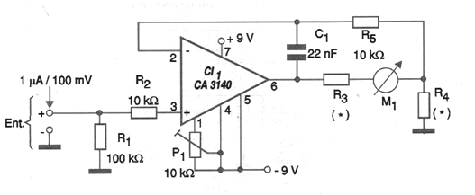
If the reader needs to monitor a voltage and does not want an expensive or sophisticated solution. In fact, you even found an analog galvanometer (microammeter or milliamperimeter) in your material stock and you want to take advantage of it, the circuit shown in the figure is an interesting solution. This circuit allows galvanometers from 50 uA to 2.5 mA full-scale to be used as voltmeters providing a reading of 1 uA for every 100 mV of input. It is clear that if the monitored voltage is different (another range), a resistive divider can be added at the entrance of the circuit. An important point to be considered in this circuit is its high input impedance, which gives it a sensitivity that can be very important in the desired application. The table given below provides the values of R3 and R4 as a function of the full-scale current of the instrument used. Note that the circuit power supply must be symmetrical.
Full-scale current of M1/R3 (ohms)/R4 (Ohms)
50 uA 47 k 2.2 k
100 uA 27 k 1 k
250 uA 10 k 470 ohms
500 uA 4.7 k 220 ohms
1 mA 2.7 k 100 ohms
2.5 mA 1 k 47 ohms
The P1 trimpot is a null adjustment that compensates for any IC signals, causing the instrument to indicate zero in the absence of input voltage.