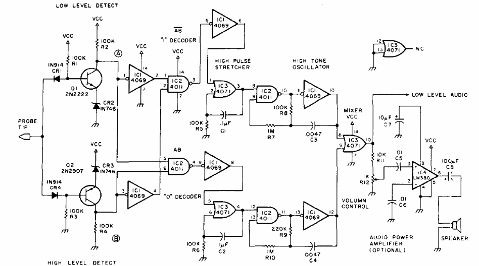
The circuit presented is a documentation for radio amateurs from 1978. Implemented with common CMOS and linear components, it indicates CMOS logic levels.
| Clique na imagem para ampliar |

The circuit presented is a documentation for radio amateurs from 1978. Implemented with common CMOS and linear components, it indicates CMOS logic levels.


