
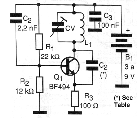
The circuit shown in Figure 1 can be used both as an experimental telegraph transmitter for the VHF and FM range, as an RF oscillator, operating between 50 and 120 MHz, depending only on the coil used.
Since it is a very simple design, the assembly can be done on a terminal bridge with the arrangement of components shown in Figure 2.

The coil will depend on the frequency range of operation according to the following table:
The coil, in all cases, is wrapped in a pencil for reference, using 24 to 28 AWG wire, without a core.
As a transmitter, a telescopic antenna of 15 to 40 cm can be used and the power can be made with voltages from 3 to 9 V.
To modulate the circuit with an audio signal, this signal can be applied to the emitter or to the base of the transistor through a ceramic capacitor from 220nF to 470nF.
To transmit telegraph signals use an audio oscillator as a modulator or simply insert the manipulator between the power supply and the circuit.
The trimmer can be of any type with a maximum capacitance of 15 to 40 pF. The maximum capacitance of this component also influences the frequency range generated and there should be possible compensations with the number of turns of the coil if the desired tuning is not achieved.
As a transmitter, the range can reach 100 meters with a 9 V supply and a sensitive receiver.
Q1 - BF494 or 2N2222 - RF transistor
L1 - Coil - see text
C1 - 2.2 nF - ceramic capacitor
C2 - see table
C3 - 100 nF - ceramic capacitor
R1 - 22k ohms x 1/8 W - resistor - red, red, orange
R2 - 12 k ohms x 1/8 W - resistor - brown, red, orange
R3 - 100 ohms x 1/8 W - resistor - brown, black, brown
CV - trimmer - see text
B1 - 3 to 9 V - batteries or battery
Miscellaneous:
Terminal bridge, assembly box, wires, power supply or battery holder.


