
One way to get great sensitivity for a relay is by releasing it through an electronic circuit. The circuit we show in Figure 1 has precisely this purpose.
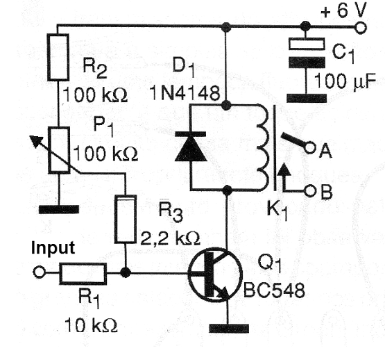
With it, minimum volt-fraction voltages and micro-amperage order currents can trigger a common 6 V relay. If the relay has two contacts, we can use the second relay to add a locking system.
With the locking system, a brief pulse at the input closes the contacts of the relay thus maintaining it indefinitely. To disarm the relay, you must turn off the power for a moment.
In Figure 2 we have the way of making the assembly using a matrix of contacts or a universal board with the same pattern.
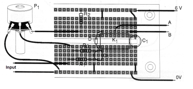
Note that a DIL-based relay was used similar to a 14-pin integrated circuit. What can be controlled by this circuit depends on the contact capacity of the relay used.
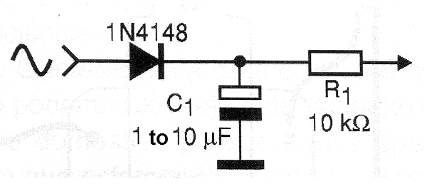
P1 must be set so that the relay is at the trigger threshold. By adding the circuit shown in Figure 3, the relay can be activated by alternating current signals.
The relay used has a coil current up to 100 mA and equivalent transistors can be used without problems. PNP transistors can also be used with a reverse polarity of the feed and the diode D1.
Q1 - BC548 or equivalent - general purpose NPN transistor
D1 - 1N4148 - general purpose diode
P1 - 100 k ohms - potentiometer
R1 - 10 k ohms x 1/8 W - resistor - brown, black, orange
R2 - 100 k ohms x 1/8 W - resistor - brown, black, yellow
R3 - 2.2 k ohms x 1/8 W - resistor - brown, black, red
K1 - 6 V to 100 mA relay
B1 - 6 V - 4 batteries or power supply
C1 - 100 uF x 12 V - electrolytic capacitor
Miscellaneous:
Contact matrix or universal printed circuit board, battery holder, wires, welder, etc.


