
ART2957S ART176
Speakers reproduce sounds by moving a cardboard or plastic cone back and forth when the coil coupled to this cone is traversed by a current supplied by the amplifier, as shown in Figure 1. The air in front of and behind the speaker is compressed and decompressed, creating a disturbance that propagates through space.
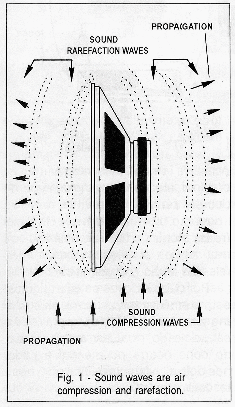
The force to which the cone is subjected therefore depends on the direction of current flow in its coil and the polarity of a permanent magnet.
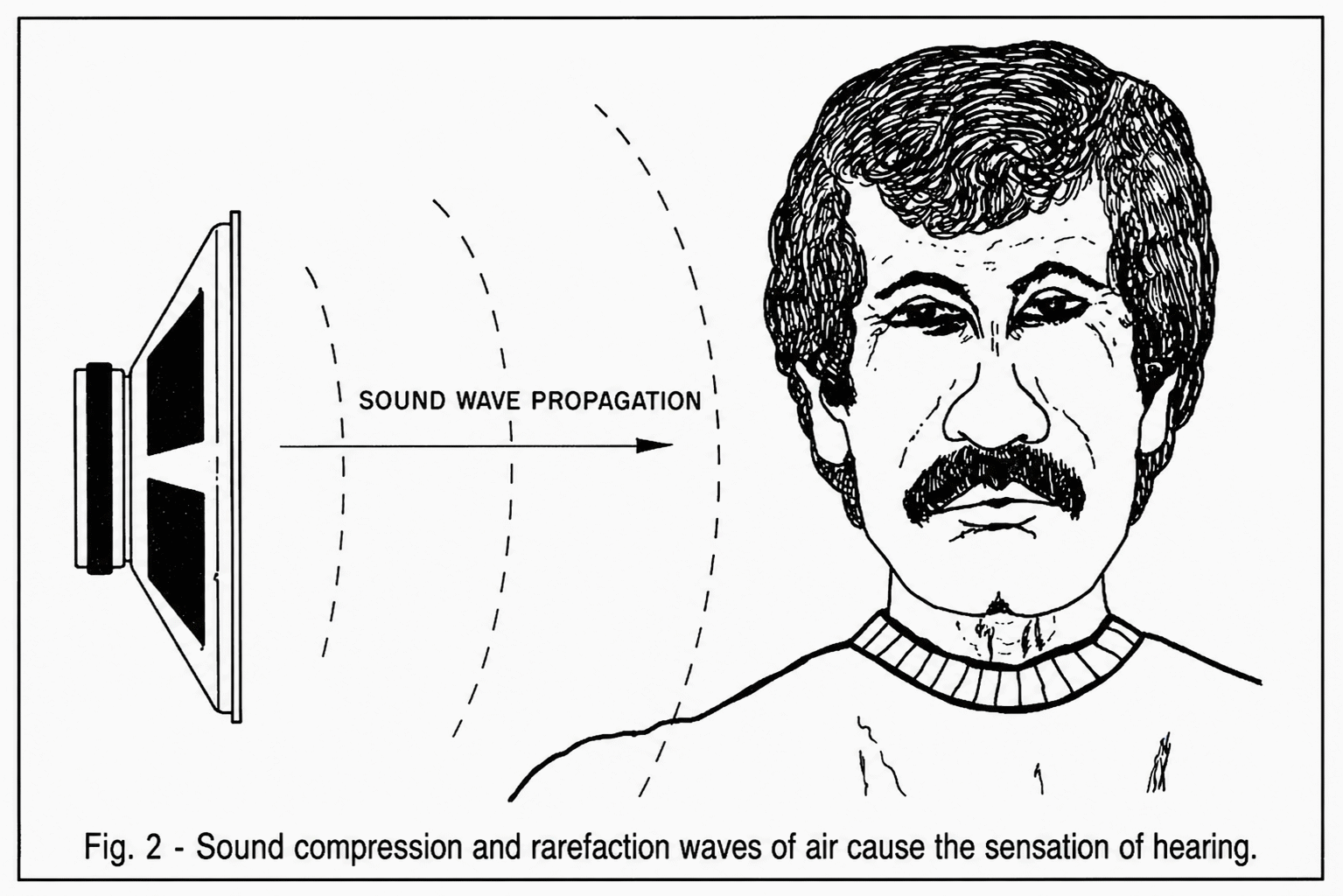
If we have a single loudspeaker reproducing a sound signal, the polarity of the signal is not important because the effects obtained when the air is moved in one direction or the other are the same for our ears: in both cases, as shown in Figure 2, a sound disturbance is created with the waveform of the original sound that propagates to our ears.
However, if we have two loudspeakers that must reproduce the same signal, it is very important that this occurs with a coordinated movement of their cones.
Thus, if the cones tend to move in opposite directions with the same half-cycle of a signal, as shown in Figure 3, a phenomenon of "destructive interference" occurs.
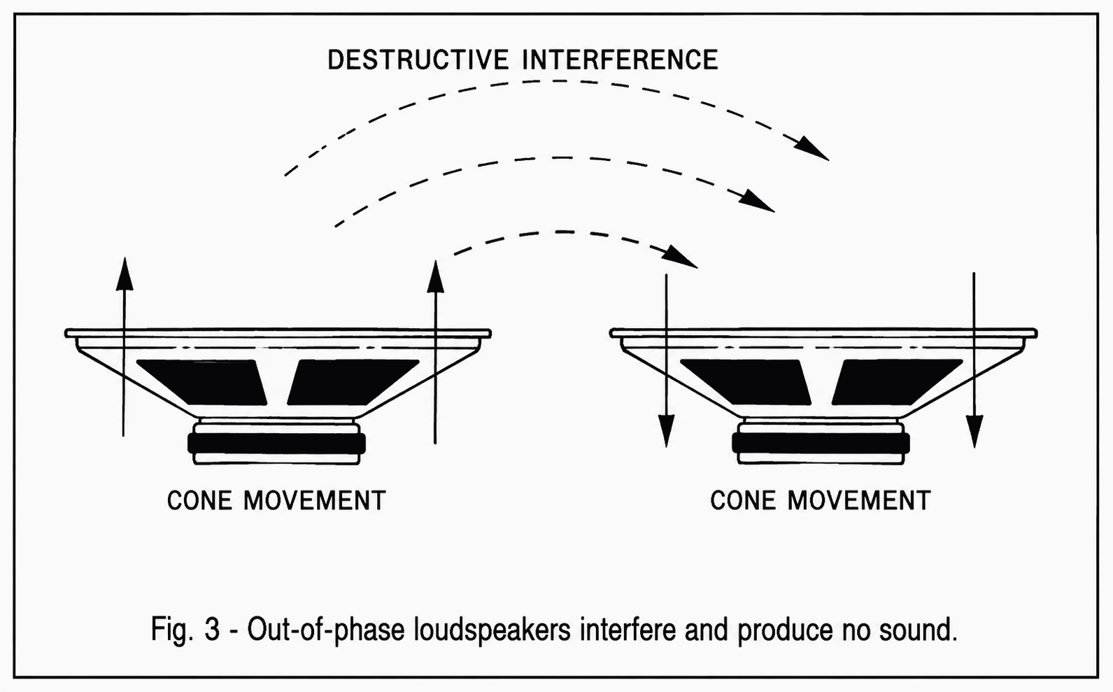
At points where one speaker experiences the greatest degree of air compression, the other speaker, moving in the opposite direction, causes decompression. In other words, the signal is canceled out at this location.
If the two speakers are very close together or in the same speaker enclosure, the connection that causes them to function in this way is highly detrimental to the quality of the sound reproduction.
the other hand, if the movement of the cones is such that we have air compression in the same half-cycles, the sound reproduction efficiency will be much higher, as shown in Figure 4.
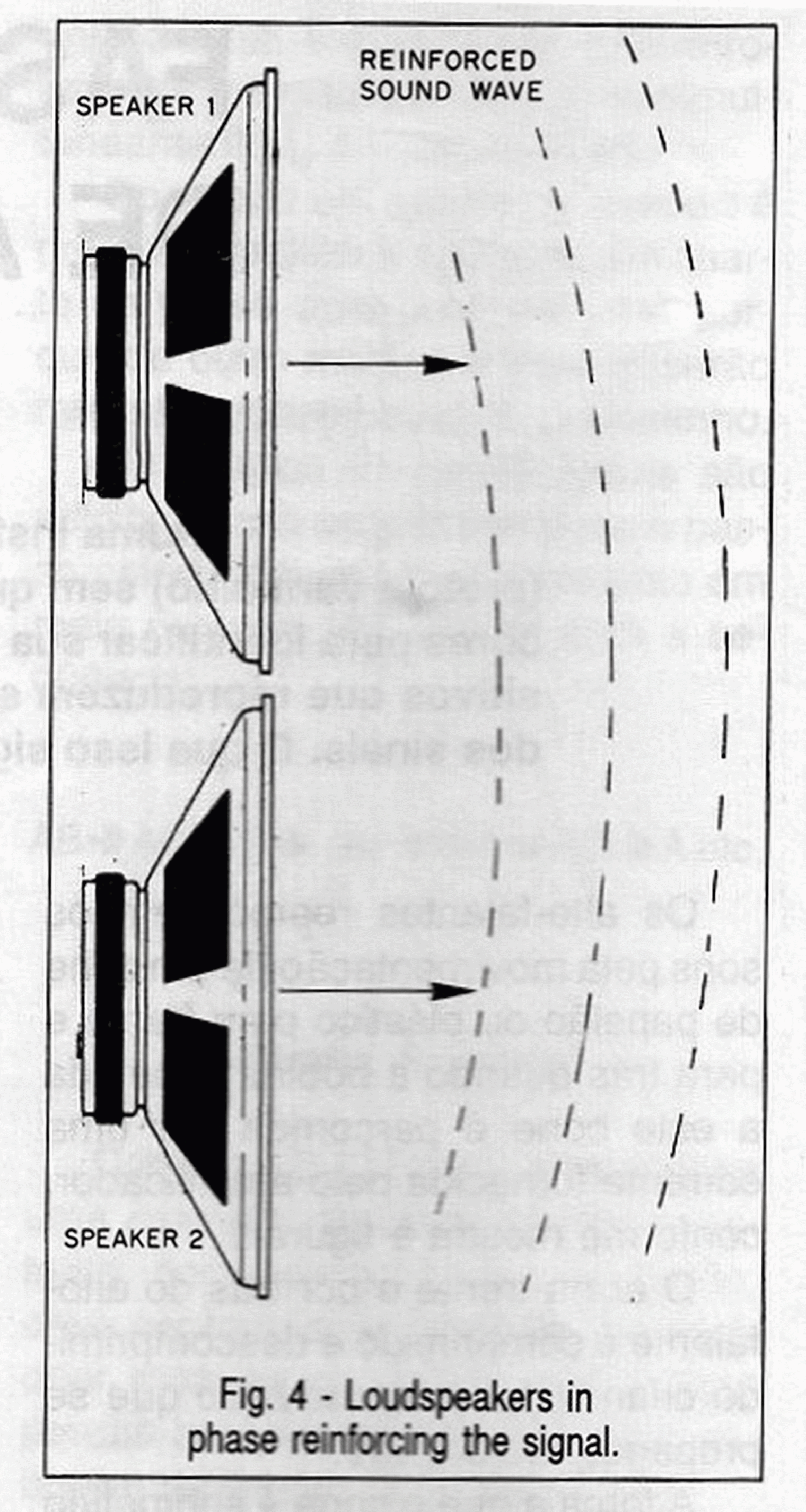
In the first case, where the cones move in opposite directions, we say that the speakers are out of phase, while in the second case we say that the speakers are in phase.
How can we ensure that the speakers have their cones moving in the same direction with the same half-cycle of an audio signal?
To prevent the connection of two or more speakers to the same amplifier channel from leading to uncontrolled reproduction, i.e., out of phase, the speakers are equipped with markings that allow them to be connected in phase.
What is done then is to apply a signal to the speaker, for example from a simple battery that causes a current to flow in a known direction through its coil, as shown in Figure 5.
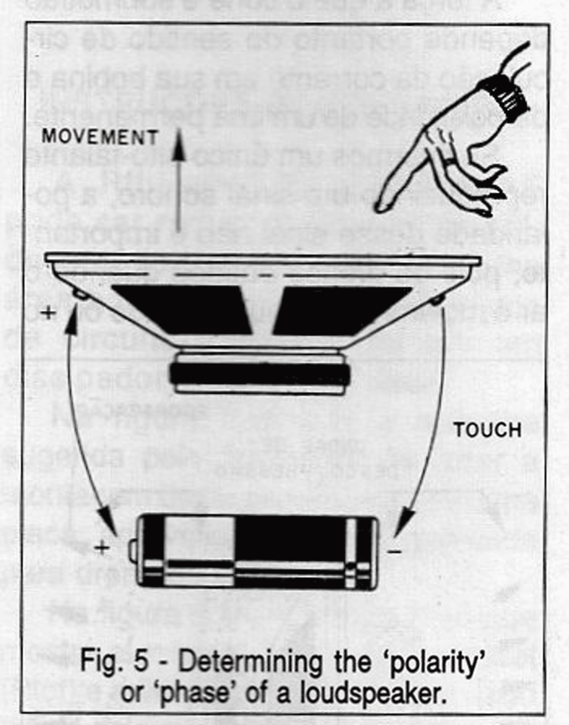
If, with the application of this current, the cone moves forward, the positive terminal of the battery will be connected to the positive terminal of the speaker.
Note that the (+) marking on a speaker terminal has nothing to do with polarity or the obligation to fix a direction of current flow.
The (+) only indicates that, if at a given moment we have a signal that is positive relative to the other terminal, the cone will move forward.
However, what is important for the speaker installer is to observe that in a set of these elements, by marking the polarity or phase, we can ensure that the movement of all always occurs in the same direction.
Thus, if we have speakers in series, for example two of them, as shown in Figure 6, we have two possibilities for the connection.
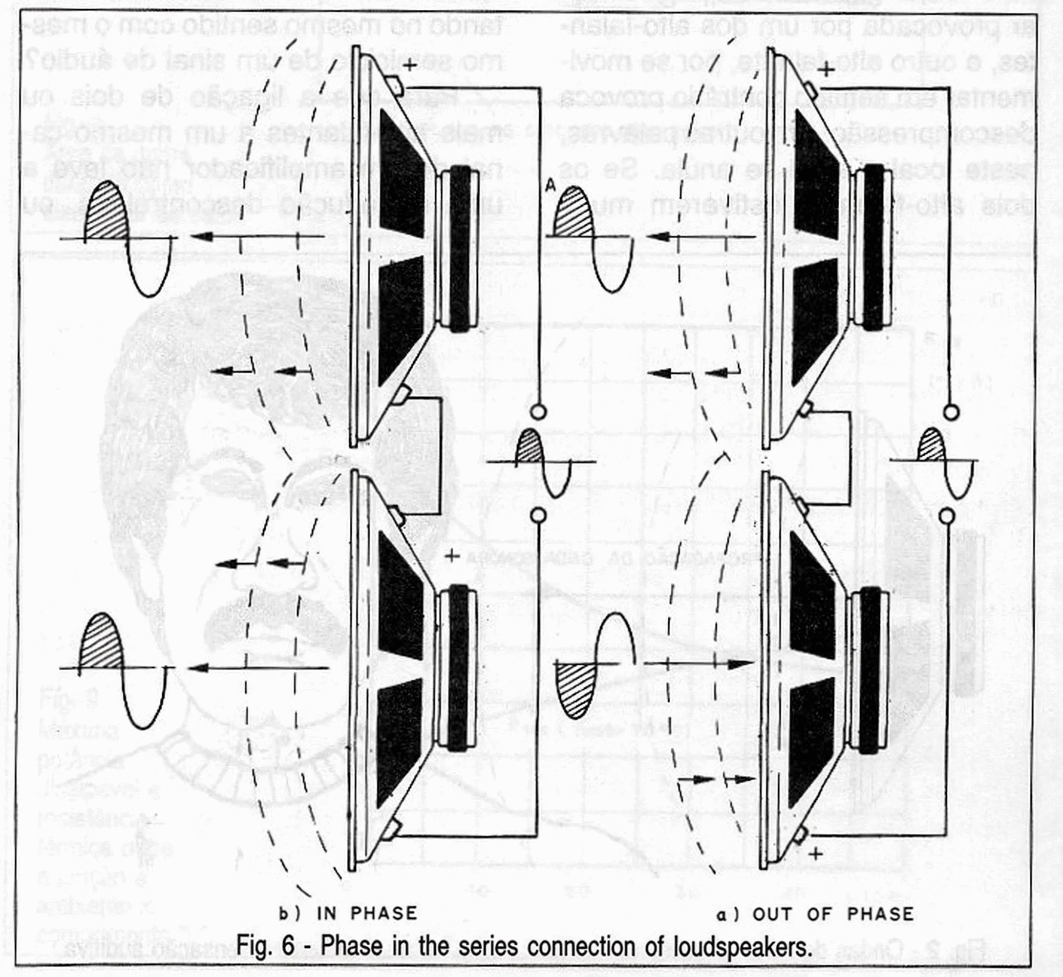
In the first case, the (+) signs are in positions such that for each half-cycle of the signal, they will always be traversed in opposite directions; that is, while one has the cone moving forward, the other has it moving backward. Under these conditions, we say that the speakers are out of phase.
On the other hand, if the speakers are connected as shown in the same figure in (b), for each half-cycle of the signal, the cone movement occurs in both speakers in the same direction.
In this case, we say that the speakers are in phase.
Therefore, it is important to observe this type of connection, for example, in a car or in a speaker box, which are environments where we need to ensure that the speakers are in phase to avoid distortion problems or loss of performance.
The same applies to speakers connected in parallel, as shown in Figure 7.
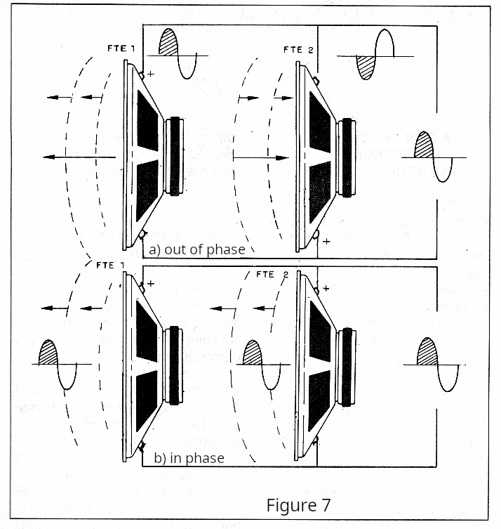
In the first case, the speakers are out of phase, since in the same half-cycle of the signal, the movements of the cones occur in opposite directions.
For the in-phase connection of two speakers, we have the connection shown in (b) of the same figure.
Everything we have seen is valid for a larger number of speakers, as shown in figure 8.
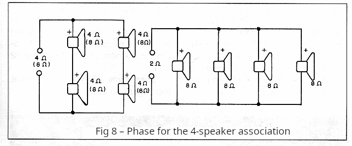
In practice, it is easier to observe the phase connection by referencing the colors of the amplifier's connecting wires, since the signal output is also polarized in the same way. This is why black and red wires are used for speaker outputs.
However, it's not enough for the speakers in a system to have the correct phase connection.
If we have several speakers connected to the same amplifier channel, it's important that there is a correct distribution of power among them, and this means that in addition to having the same electrical characteristics, they must also have the same mechanical characteristics.
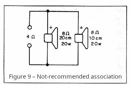
Therefore, it is not advisable to connect speakers of different power ratings and sizes in parallel, even if their impedances are as desired, as shown in Figure 9.
What happens is that different loudspeakers have different response curves, as shown in Figure 10.
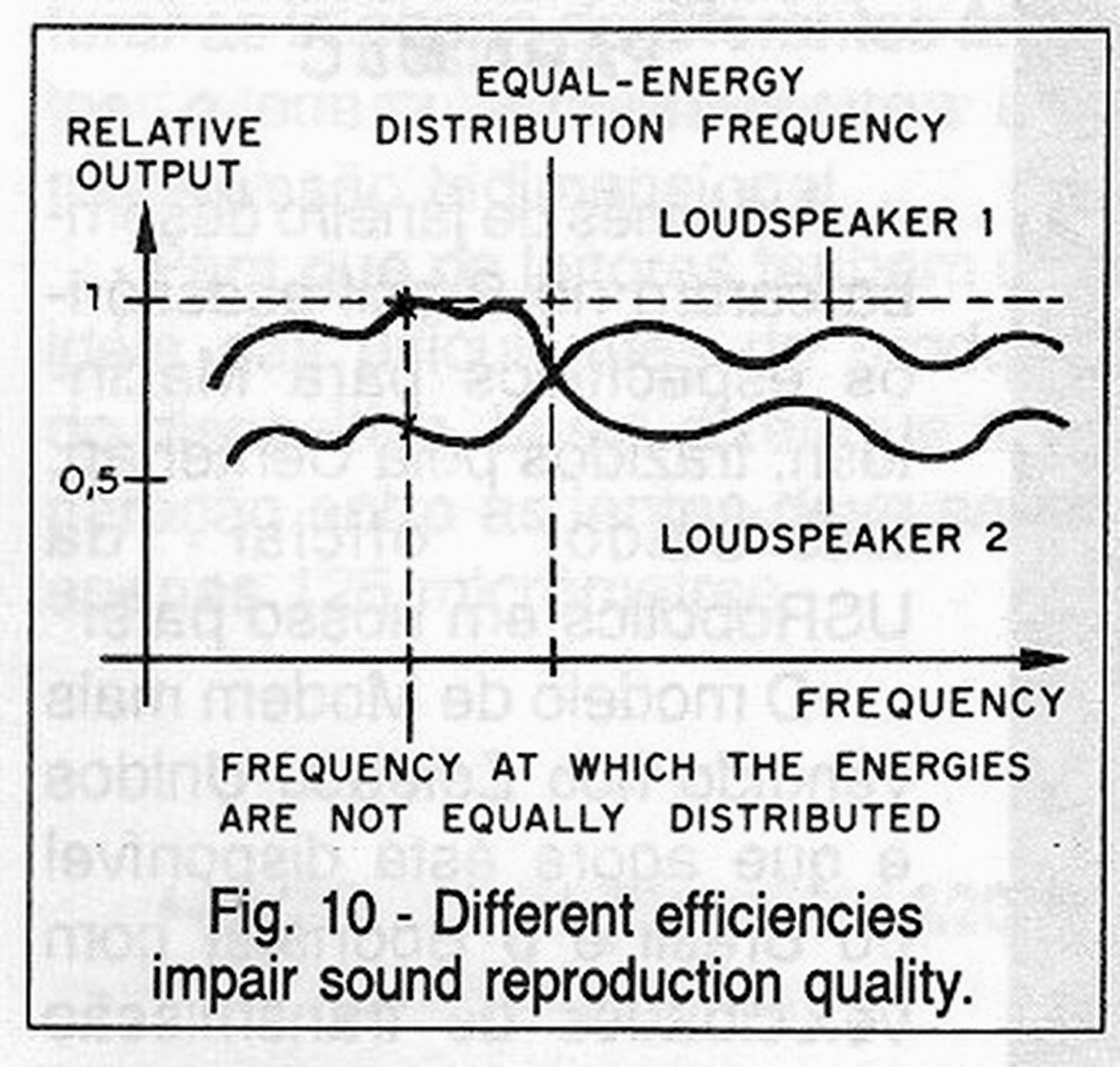
Thus, for a given signal frequency, for example 1 kHz, the speakers will have different impedances and therefore different efficiency. The distribution of the amplifier's energy, under these conditions, will be unequal, and one of the speakers will have a lower reproduction level than the other. In other words, under these conditions, the speakers will behave differently in the sound reproduction range.
Obviously, the power ratings of the speakers must be taken into account because they should always receive a signal smaller than what they are capable of reproducing. If the applied power is greater than what they can handle, the result may be damage.


