
ART2426 ART1988S
A solenoid is used to activate the closing mechanism of a trap. The triggering occurs when the animal cuts a beam of light that hits a sensitive electronic sensor. The electric trap is powered by a voltage of 110 V or 220 V and is quite simple to assemble. You can use it at home to capture rats, pigeons, sparrows, or even in research to capture other animals, always respecting the legislation and remembering that the circuit must be powered from the mains.
The recommended solenoid is salvaged from a washing machine, but there are alternatives that will be described in the article itself, some of which are quite economical. The assembly of the system is simple, requiring only one mechanical part that will not present problems for skilled readers who possess some basic tools.
How it Works
The system is quite simple, as we can see from the block diagram in Figure 1.
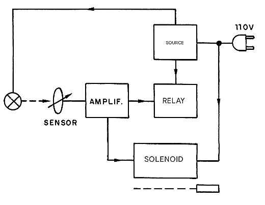
The sensor consists of an LDR that is illuminated by a common 12-volt x 200 mA lamp (car courtesy light). When the animal enters the trap, the light beam is interrupted, triggering the circuit. The trigger point is pre-adjusted using a trimpot.
With the trigger, a relay closes its contacts, which can activate a high-voltage solenoid (110 V or 220 V), of the type found in washing machines, or even a smaller solenoid, as we will explain later. The movement of the solenoid core activates the trap's closing mechanism. A buzzer can be used so that, when the trap closes, the user is notified.
Assembly
Figure 2 shows the complete diagram of the trap.
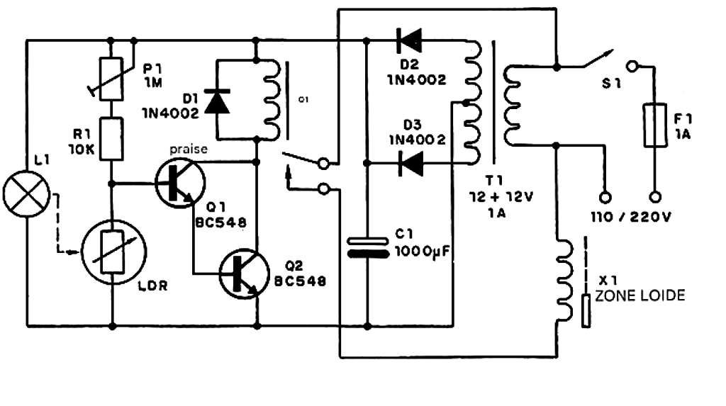
The assembly can be done either on a terminal strip or on a printed circuit board.
Figure 3 shows the assembly on a terminal strip.
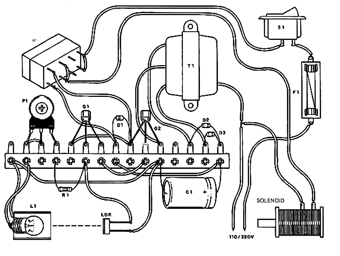
This terminal strip can be enclosed in a box to avoid contact problems with the components or short circuits. Figure 4 shows the assembly of the mechanical part of the trap.
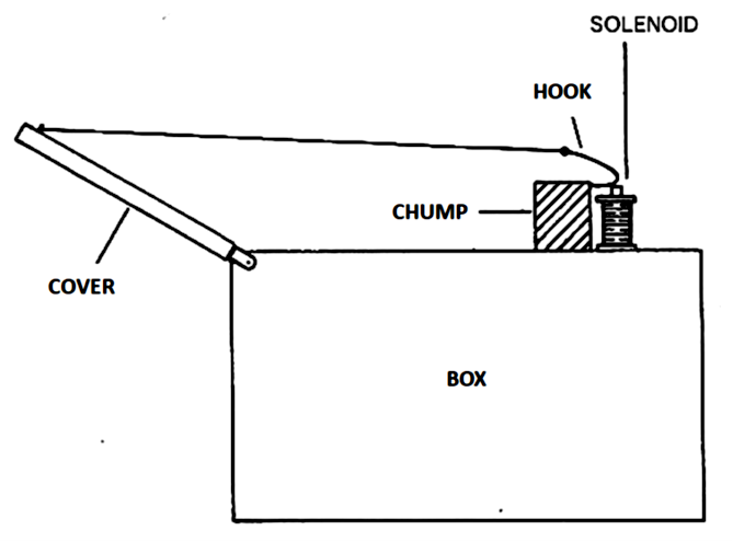
Note that the movement of the solenoid core into its interior should release the trap cover, which closes due to its own weight. A weight-operated latch should be provided, and there are several possibilities for this. For the solenoid, we have another alternative, such as using a 12-volt relay core, as shown in Figure 5.
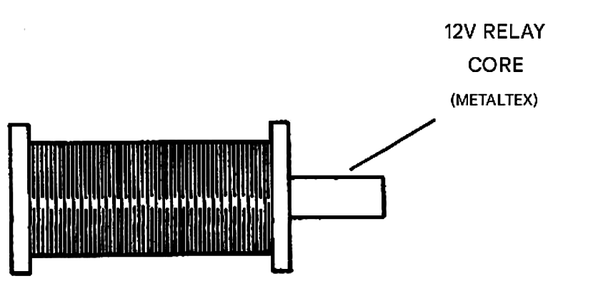
This relay is powered by the circuit's own low voltage. It is expected that this solenoid system will have much less power than a solenoid from a washing machine, but here there is an important possibility: powering the system with 12V from a battery or even a set of large batteries. A household doorbell can also be adapted to be used as a solenoid, but it is necessary to note that it should not remain on for too long as it heats up quickly.
A common incandescent lamp, from 40 watts to 60 watts, can be connected in series to avoid this heating. The reader should experiment in this case, as the behavior of the system may change depending on the adapted doorbell. When assembling the electronic part, the reader must observe the polarity of the diode and electrolytic capacitors, as well as the position of the transistors. The LDR is a common round one of any type.
Its assembly should preferably be done in an opaque tube to avoid the influence of ambient light. The electrolytic capacitor must have a minimum working voltage of 16 volts. Values close to 1200 uF or even 1500 uF can be used, and in the case of battery power, its value can be reduced to 100 uF or less.
In this case, diodes D2 and D1 are eliminated, as is the transformer. The fuse is 1A, but this value depends on the solenoids. It can be increased if the solenoid is of higher power.
Testing and Use
Testing and adjusting the trap is simple. Turn on the unit and adjust P1 so that the relay remains open when light is shining on the LDR. The point of greatest sensitivity occurs when the relay is about to close, now when an object passes between the LDR and the lamp. Once adjusted, simply check the mechanical part.
List of Materials
Q1, Q2 - BC548 or equivalent – general-purpose NPN transistors
D1, D2, D3 - 1N4002 or equivalent - general-purpose diodes
K1 – 12 V relay
P1 - 1M - trimpot
T1 - Transformer with 110V or 220V primary depending on the mains voltage and 12V x 500mA or 1A secondary, with center tap
F1 - 1A - fuse
S1 - Simple switch
L1 - 12 x 200mA - car interior lamp
LDR - common round LDR
X1 - washing machine solenoid (see text)
R1 – 10k x 1/8W - resistor (brown, black, orange)
C1 - 1000 uF x 15V - electrolytic capacitor
Miscellaneous: trap box, power cable, and opaque tubes for the LDR and for the lamp, solder, fuse holder, terminal block or printed circuit board, etc.


