
ART1482S ART2283
Using the CA1458E integrated circuit, which consists of a dual operational amplifier (each equivalent to the well-known 741), and a 4 A power Darlington transistor, we have developed a very useful resistive load for testing power supplies and other circuits that require resistors with low values and high dissipation. This load can operate with voltages up to 60 V and dissipate power on the order of 50 W.
The accuracy of the simulated value depends exclusively on the resistor used as a standard and the resistors used in the circuit assembly, which, preferably for a professional application, should be 1%. The circuit can be powered either by common 9 V batteries or by a fixed power supply, the diagram of which is given in Figure 1, which provides a 12 V output.
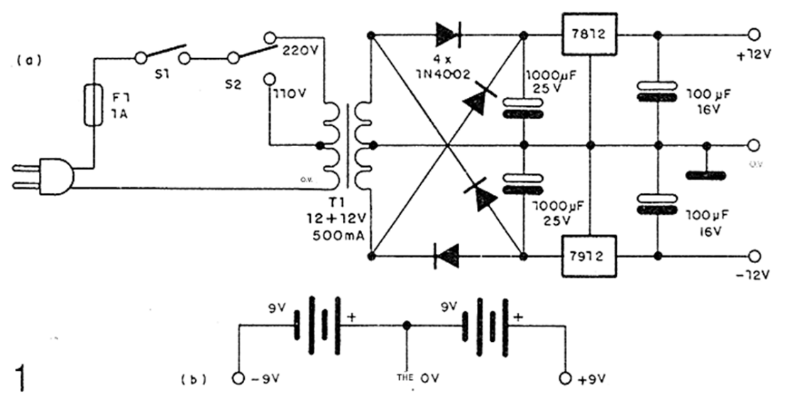
Since the current consumption of the operating sector, which is powered by the source or batteries, is very low, small 9V batteries will have good durability, thus allowing for the construction of a portable device.
THE CIRCUIT
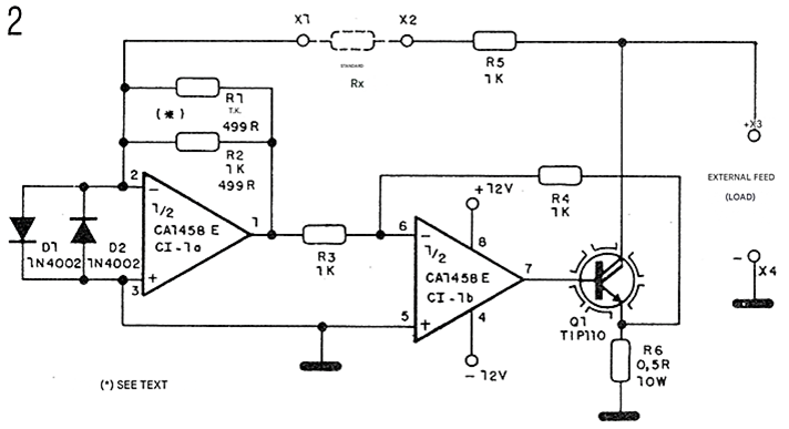
The basic idea consists of programming the resistive value that the circuit presents through an external standard resistor Rx.
Operational amplifiers are then connected to provide a 1000x amplification, which means that the value of the external resistor will be divided by 1000. Thus, considering that there is an additional resistance of 10 ohms intrinsic to the circuit, if we connect a 12 kΩ resistor between pins X1 and X2, the resistance that will be seen between X3 and X4 will be:
(12000/1000) + 1 = 12 + 1 = 13 ohms
The maximum allowed current is determined by the characteristics of the output Darlington transistor, in this case 4A, so the dissipation in this case will be on the order of 50 W. Note that the gain of the operational amplifiers is given by the feedback resistors.
Taking the circuit as a reference, we see that the feedback resistance that determines the gain must have a non-commercial value of 499 ohms. To obtain this value, we can simply select two 1kΩ resistors that, connected in parallel, provide this value. We can take the measurement with a high-sensitivity multimeter to obtain similar accuracy for the load.
It is important to note that the resistance represented by the power transistor is biased, meaning there must be a positive voltage at the collector, relative to the emitter, for the system to function. In this case, the voltage can have a minimum value of 3 V and a maximum value determined by the characteristics of this transistor.
ASSEMBLY
Figure 2 shows the complete diagram of the resistive power load.
The component layout on the printed circuit board is shown in Figure 3.
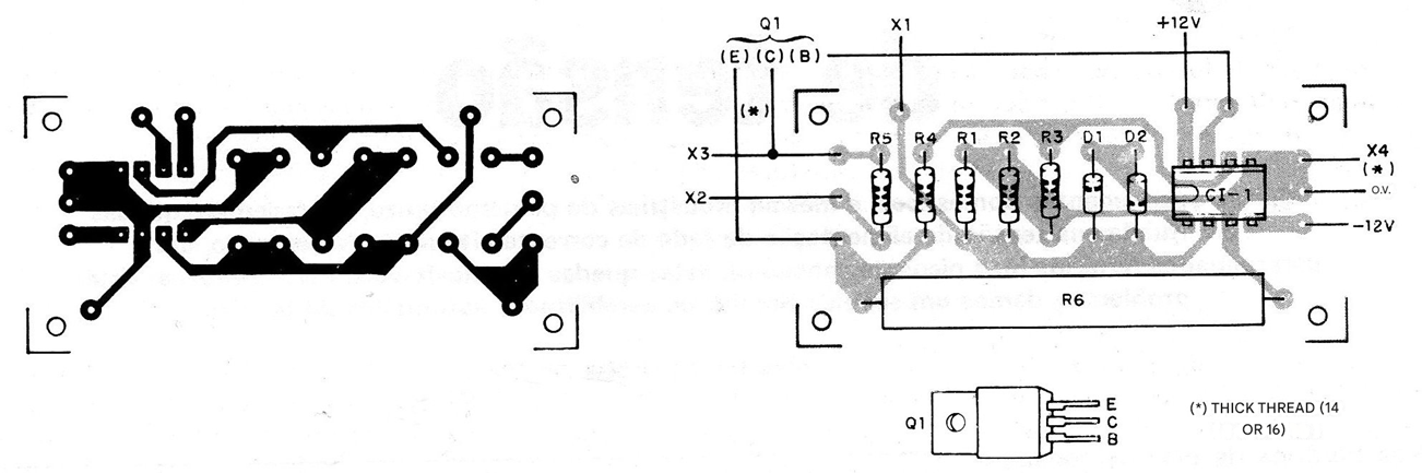
Note that the connections carrying the most intense currents should be made with thick wires or have wide copper areas on the printed circuit board. The resistors used are 1%, or according to the desired precision, and the diodes are 1N4002 or equivalent. The power transistor must be installed on an excellent heat sink.
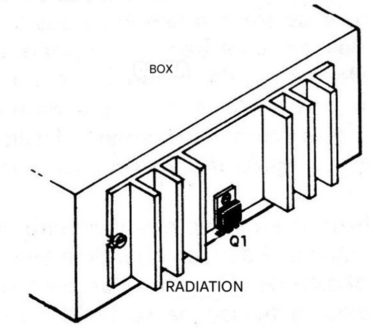
The use of thermal paste between the transistor and the heat sink is important, and the location in the case should be such that it allows for easy heat transfer to the environment. We suggest installation outside the case on its rear side, as shown in Figure 4.
Resistor R6 also tends to heat up during full power operation, so this component cannot be near heat-sensitive circuit elements.
TESTING AND USE
The accuracy of operation can be verified by connecting the load to a source and an ammeter in series, as shown in Figure 5.
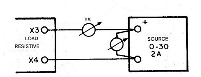
By placing a 100 kΩ resistor, for example, between X1 and X2, the load will have an equivalent resistance of 100 ohms. With a voltage of 10 V, we should have a current of 100 mA. For a 10 kΩ resistor, the equivalent resistance will be 11 ohms, which means that with a voltage of 11 V, we will have a current of 1 A.
One suggestion is to use a linear potentiometer between X1 and X2, which would allow adjustment of the load current over a wide range of values. Once operation is verified, simply use the load, remembering its current and voltage limitations and observing its polarity. Figure 6 shows how to perform a power supply functionality test.
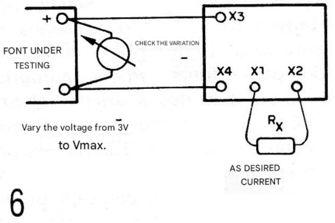
We adjust the external resistance to a value that results in the current at which we want to test the power supply.
LIST OF MATERIALS
IC-1 - CA1458E - integrated circuit (Dual operational)
Q1 – TIP110 - Darlington power transistor
D1, D2 - 1N4002 - silicon diodes
R1 to R5 – 1 kΩ - resistors (brown, black, red) - see text
R6 - 0.5 ohms x 10 W - wirewound resistor
Miscellaneous: printed circuit board, heatsink for the transistor, wires, solder, power supply, enclosure, etc.


