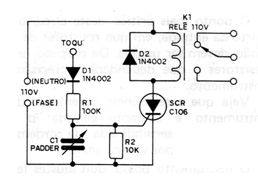
We found this circuit in a 1983 publication. It is a simple touch alarm circuit using a SCR type C106 or equivalent. Note to the reader that, in this circuit, the SCR trip triggers the relay directly from the local power grid. The relay used is then of the type for 110 V, with coil current less than the SCR capacity, that is, less than 1 A. C1 is a sensitivity adjustment to avoid triggering the SCR with transients. The D2 diode is a protection for the SCR, preventing the voltage induced in closing the relay from causing damage to the SCR. The sensor can be a bare piece of wire or a metal plate. R1 should be as high as possible to avoid a shock hazard. The reader used a 100k resistor for this function, but higher values can lead to positive results. Note that the position of the neutral and the phase of the socket is important in the connection for the circuit to work. If the reader connects your device to the outlet and it does not work on the first attempt, simply invert the position of the outlet.