
ART1327S ART5612
Note: Article published in Saber Eletrônica magazine 443, December 2009.
The choice of a precision resistor for an application involves more than just observing its tolerance. The equipment in which they will operate is subject to variations in physical conditions, such as temperature, humidity, etc., which can have significant effects on their value.
Thus, modern technologies used in the manufacture of precision resistors also include the introduction of characteristics that mean not only "precision," but rather "precision within a very wide range of variations in operating conditions," and even the possibility of such resistors working together, as happens in voltage dividers. One of the technologies used to manufacture such resistors is called Thin Film, which we will analyze below in details.
The Films
The films used in the manufacture of resistors have a thickness of approximately 500 microns. By using masks that allow altering the widths and spacing of the films, a wide range of ohmic values can be obtained. Resistivity standards can vary between 50 and 2000 ohms per square. As a rule, the lower the resistivity of the sheet, the better the electrical performance.
The main materials used are:
• Nichrome (NiCr): This is the most popular material and has the best specifications in terms of TCR (Temperature Coefficient of Resistance), noise, and long-term stability. Its typical resistivities are 50, 100, and 200 ohms per square.
• Tamelox: This is a Vishay alloy that combines the advantages of Nichrome and Tantalum Nitride.
• Tantalum Nitride (TaN2): When processed and deposited correctly, this substance results in an alloy resistant to environmental impurities. Its electrical performance is not as good as that of nichrome. It is preferred for low-power applications and where there is no self-heating, as well as high relative humidity.
• Silicon Chromite (SiCr): This material has a very high resistivity (2000–3000) and is used to obtain high resistances in small areas. Electrical specifications such as TCR, long-term stability, and voltage coefficients are superior to those found in thick-film technology.
Integrated Thin Film Construction
The term integrated is borrowed from the semiconductor industry and is used similarly. An integrated circuit consists of a grouping of elements that are formed and interconnected on a common substrate to form a functional network. Integrated resistors follow the same concept: a group of resistive elements is manufactured in a single process and interconnected on a common substrate.
Resistors are also manufactured by an optical lithography process, followed by selective removal of undesirable materials. An important characteristic of this process is uniformity. As all resistors are manufactured simultaneously and subjected to the same processes, with several wafers being treated at the same time, thousands of components with virtually identical characteristics are obtained.
Resistance Range
The lithography process allows the manufacturer to obtain components in a wide range of resistance values. The component's resistance basically depends on the characteristics of the film and the pattern in which it is deposited. However, certain space limitations must be taken into account, in addition to the need to add terminals. By using films in the range of 50 to 2000 ohms/square, the resistance range of the resulting components can vary from a few ohms to several megohms. However, the most common values are between 250 ohms and 100 kohms.
Very Low Resistances
One problem that arises is that when manufacturing resistors with very low values, the resistance of the terminals must be considered. With proper design, the effects of the terminals can be minimized, but not completely eliminated, as illustrated in Figure 1.
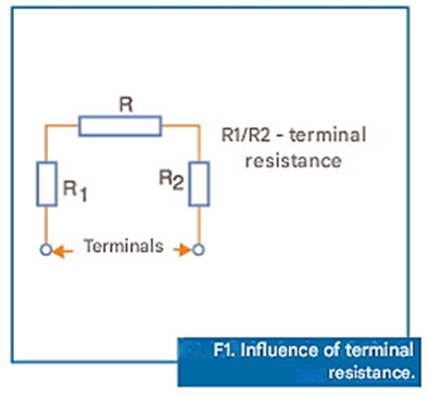
In a 10-ohm resistor, the effect of terminal resistance can reach 1%, while this value is only 0.01% in a 1 kohm resistor.
Resistance Tolerance
The use of modern LASER systems allows adjusting resistor values to achieve very low tolerances, with absolute and relative values reaching 0.01% and 0.005% respectively. The lower the tolerance, the more carefully the resistor must be designed to obtain a distribution of values within the tolerance limits, with a compensating cost and manufacturing time. One way to achieve this is using special geometries for adjustments, see Figure 2.
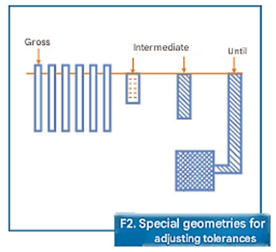
These geometries reduce the resistor's sensitivity to the amount of material that must be removed in the adjustment process to achieve the desired precision.
TCR - Temperature Coefficient of Resistance
The Temperature Coefficient of Resistance, or TCR, measures the variation in resistance as a function of ambient temperature. It is defined as the change in resistance per unit change in temperature and is commonly expressed in parts per million per degree Celsius, or ppm/°C.
Common resistors, similar to discrete resistors made with metal films, are classified by batches according to their TCR. However, modern technologies, such as those using thin films, have resulted in what are called "third-generation" thin-film products, which have TCRs lower than 10 ppm/°C absolute.
The TCR is generally determined experimentally by measuring the resistance at various temperatures and calculating the rate of change over a given range, typically between 25 °C and 125 °C. If the resistance varies linearly with temperature, then the TCR will be constant over the considered range. However, if the variation is not linear, as occurs with nickel/chromium alloys, then the TCR will be expressed by a curve, as shown in Figure 3.
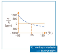
According to the method specified in the MIL-STD-202 standard — Method 304, the TCR must be measured in intervals between 25 °C and 55 °C and also between 25 °C and 125 °C. The highest value recorded should be indicated as TCR. Understanding the effects of alloy composition and through careful control in processing (it is possible to model the resistance vs. temperature curve) of a product in several ways, observe Figure 4.
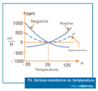
We can have curves: negative throughout the range, positive throughout the range, or even negative at one extreme and positive at the other, of the temperature range.
Tracking
There are applications where the accuracies of the resistors used need to be "paired," that is, the variations of one (as a function of temperature) must follow the variations of another in a network used in the same circuit. Thin-film networks have excellent "tracking" characteristics. However, several aspects of this behavior need to be understood and differentiated.
TCR Tracking
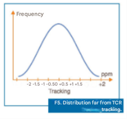
TCR tracking is defined as the difference between the TCR of a pair of resistors in a given temperature range. For common discrete resistors, it is difficult to obtain an absolute distribution very close to the TCRs, see example in Figure 5.
On the other hand, by the integrated process, given similar deposition conditions (uniformity, etc.), a distribution closer to the TCR tracking can be achieved, as illustrated in Figure 6.
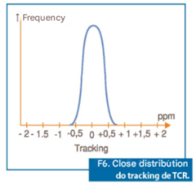
The small differences that exist occur due to process variables such as substrate defects, non-uniform deposition, different thermal gradients during production, non-uniform stress, etc.
Resistance Tracking in Switching
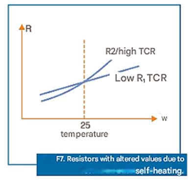
Many circuits operate in a way where the current through a resistor is switched on and off, while in another (of the same circuit) it operates with a constant current. In this case, even if the resistors have the same TCR and the substrate is kept at a uniform temperature, the resistances may change due to self-heating. In these situations, the resistors must have an absolute TCR that is as low as possible in the operating temperature range, and they need to be mounted as close to each other as possible to minimize temperature differences between them. Figure 7 shows .
Voltage Ratios
Resistors are often used as voltage dividers. In these cases, if high precision is required, it is more important to think in terms of voltage ratio than resistance ratio. There are three important aspects of voltage ratios that should be understood in comparison to resistance ratios. These are: the voltage ratio itself, voltage ratio tolerance, and voltage ratio tracking. The voltage of a divider, as shown in Figure 8, is ideally calculated by the formula:
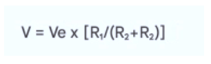
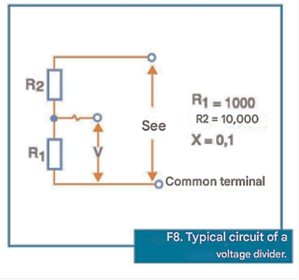
When the resistance values are not equal, the ratio between the voltages will differ from the calculated value by an amount, which will depend on the resistance of the common terminal. When low-value resistors are used, the difference can be significant. For example, for a 10 kohm resistor in series with a 1 kohm resistor, having a common terminal with 100 mohms resistance, the differences between the ratios can differ by 75 ppm, as demonstrated by the calculations below: what happens to resistors in such a case.
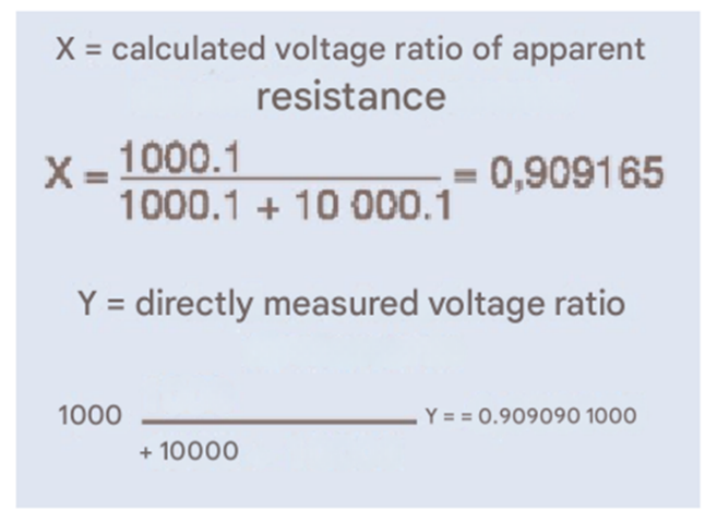
For a 1 kohm resistor in series with a 100 ohm resistor, the 100 mohm tap resistance causes a voltage ratio difference of more than 800 ppm.
Voltage Ratio Tolerance
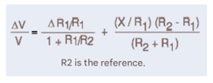
The tolerance for a given voltage ratio also differs from the tolerance for the same resistance ratio. The biggest difference, in this case, is given by the first term of the equation below, which is also affected by the common terminal resistance.
Stability
The effects described above are reversible: the variations are not permanent and disappear when the temperature returns to the starting point. However, there are irreversible effects. Most resistor networks are used in voltage dividers. However, it should be considered that, throughout the component's lifespan, its characteristics change, including the tolerance, which must be preserved as much as possible. This requires film stability.
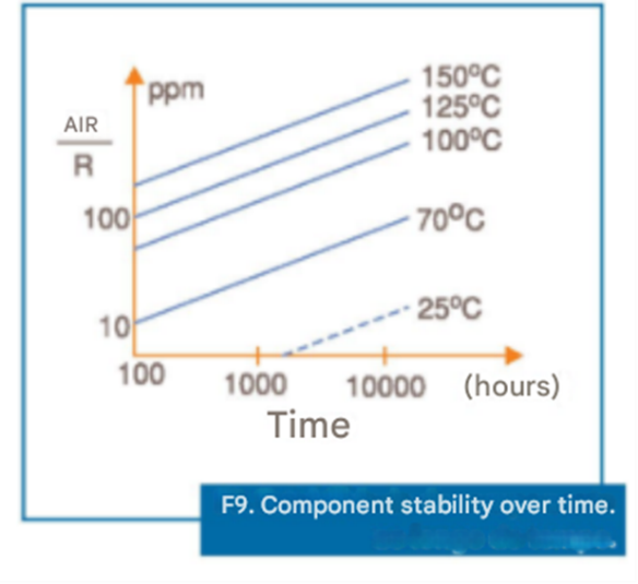
The materials used have undergone progress in the manufacturing process, thus obtaining components with greater stability. It has been observed that for Nickel/Chromium alloys, stability over time depends on the substrate temperature. This means that the component's behavior can be predicted based on just one variable.
Figure 9 shows a graph that illustrates how temperature influences the component's stability over time. The problem of TCR tracking should be considered, which will be smaller the smaller the variation in the absolute resistance of each resistor in the pair.
Dissipation
Thin-film precision resistors are not used in high-power applications. This means that methods for stabilizing the power dissipated in these components are not critical. However, limits need to be established, and this is done by setting the maximum operating temperature. The zero-power temperature (also called the maximum operating temperature) is the maximum temperature at which the component can operate for a given period without excessive changes in its characteristics.
The specified time is typically 1000 hours, and the change in characteristics is usually expressed relative to the initial tolerance. Thin-film resistors need to maintain a tolerance of 0.1%, and the temperature at zero power can typically be 150 °C. At this temperature, a resistor should have a change on the order of 500 ppm absolute or 100 ppm relative to others in the same network.
If the tolerance is 0.01%, a more appropriate temperature for zero power would be 125 °C. Figure 10 shows a graph that presents the power degradation curve of a resistor as a function of temperature.
Note that the dissipated power is only valid for temperatures up to 70 °C. After that, there is degradation, and then it varies depending on whether the resistors are hermetic or non-hermetic.
When working with surface-mount resistors, special attention must be paid to individual dissipations. This is because, within the same network, different resistors may operate at different power levels. The design must consider these differences.
Voltage Coefficient and Current Noise
There are two characteristics that can cause serious problems for designs involving precision resistors and that need to be considered when resistors are made of composite materials, but are ignored in thin-film resistors because they are not very significant. The voltage coefficient of the resistor is the change in resistance per change in voltage, expressed in ppm/volt.
It expresses the non-ohmic characteristic of thin-film resistors, and its levels are more intensely manifested only in higher-value resistors, in the megohms range. Typical values are in the range of 0.1 ppm/V.
Current noise is characterized and has a typical value of less than -35 dB.
Thermoelectric Effects
Thermoelectric voltages can be generated at the resistor terminations at different temperatures. With discrete resistors, these voltages can be problematic when temperature gradients occur, given the large dimensions of the components. However, with thin-film resistor networks, the reduced sizes and more uniform heat distribution mean that these effects are practically nonexistent.
The thermoelectrically generated voltages in thin-film resistors are typically less than 0.1 µV/°C.


