
ART3147 ART2135S
A rhythmic light system consists of a set of lamps activated by an electronic circuit from the sound of an amplifier, tape player, or other equipment. The sound controls the flashing of the lamp, making it turn on and off in the volume variations of the music being played. Our system is a little different from conventional ones for two reasons:
• It does not need to be connected to a sound system, as it operates using ambient sound via a microphone.
• It works negatively, meaning that while common devices make the lamp brighter with louder sounds, this one reduces its brightness.
The circuit is designed to control up to 800 watts of common lamps on a 110V network and 1600 watts on a 220V network.
Note that one of the advantages of not having a connection to the sound system is the safety it provides to the equipment.
HOW IT WORKS
To understand the operating principle of the device, it is convenient to divide its various stages into blocks. (Figure 1)
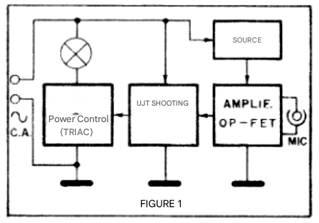
We begin with the lamp control circuit, which is based on a Triac. A Triac is a solid-state switch, that is, a high-speed switch that can be controlled by electrical signals. Depending on where we trigger it in each half-cycle of the supply voltage, we can make it conduct more or less energy, as shown in Figure 2.
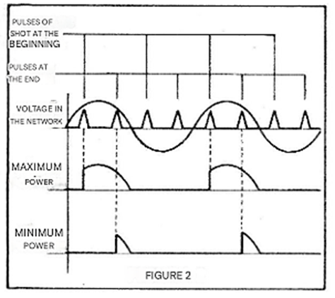
The triggering of this triac is done by the second stage, which is based on a unijunction transistor (2N2646). The pulse produced by this component is delayed in the half-cycle at a rate that depends on both the adjustment of P1 and the conduction of Q2. If Q2 is cut off (not conducting), the unijunction is triggered at the beginning of the half-cycle, and maximum power is delivered to the lamps.
On the other hand, if Q1 is saturated (fully conducting), the voltage at the emitter of Q1 takes longer to reach its trigger value, and practically no voltage is applied to the lamps, as the triac does not even trigger. Depending on the biasing of Q2 in the interval between cutoff and saturation, we can trigger Q1 at various points in the power supply half-cycle and thus obtain various gradations for the intensity of the light that is controlled.
Now, this biasing comes precisely from our last block in the basic sequence: the audio amplifier. For this purpose, we use a high-gain operational amplifier with a field-effect transistor at the input. A low-impedance microphone then picks up ambient sounds and amplifies them at a rate that depends on both R7 and R8.
The sensitivity of this stage allows the use of small loudspeakers as microphones with or without an output transformer, dynamic microphones from recorders, or even a telephone capsule. The amplifier output is connected directly to the base of Q2 via R6, providing the desired excitation for the circuit.
For cases where additional sensitivity control is desired, we recommend replacing R7 with a potentiometer of the same value or a 4M7 in series with a 100k resistor. The circuit is completed by the power supply for the amplification section, which is based on a 7812 integrated circuit. This integrated circuit does not need a heat sink, given the low current consumed by the stage.
ASSEMBLY
Figure 3 shows the complete diagram of our rhythmic light in a half-wave version.
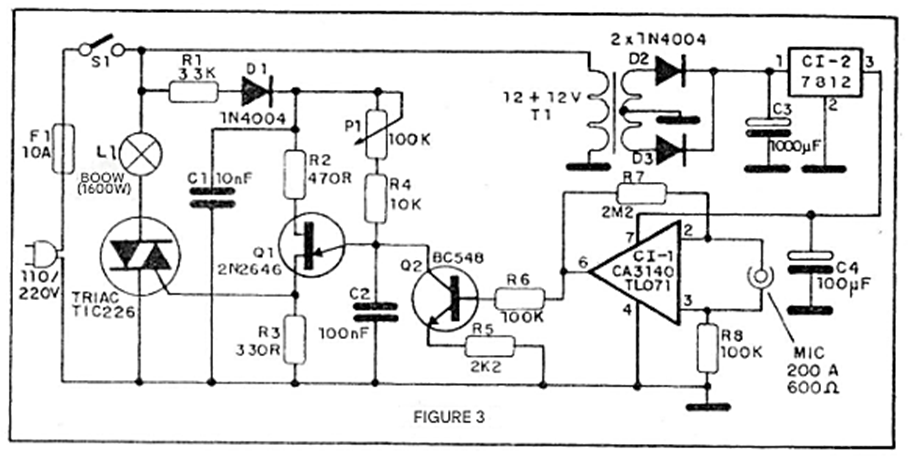
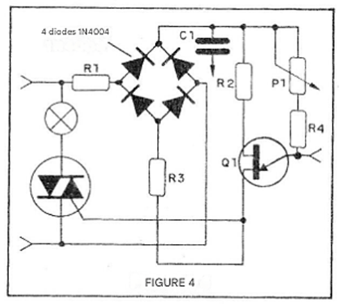
Note that, although the triac is a full-wave controller, since we do not need maximum brightness for all the lamps, we do not need to trigger it in both positive and negative cycles. For readers who want a full-wave controller, simply make the modification suggested in Figure 4.
The suggested printed circuit board for this project is shown in Figure 5.
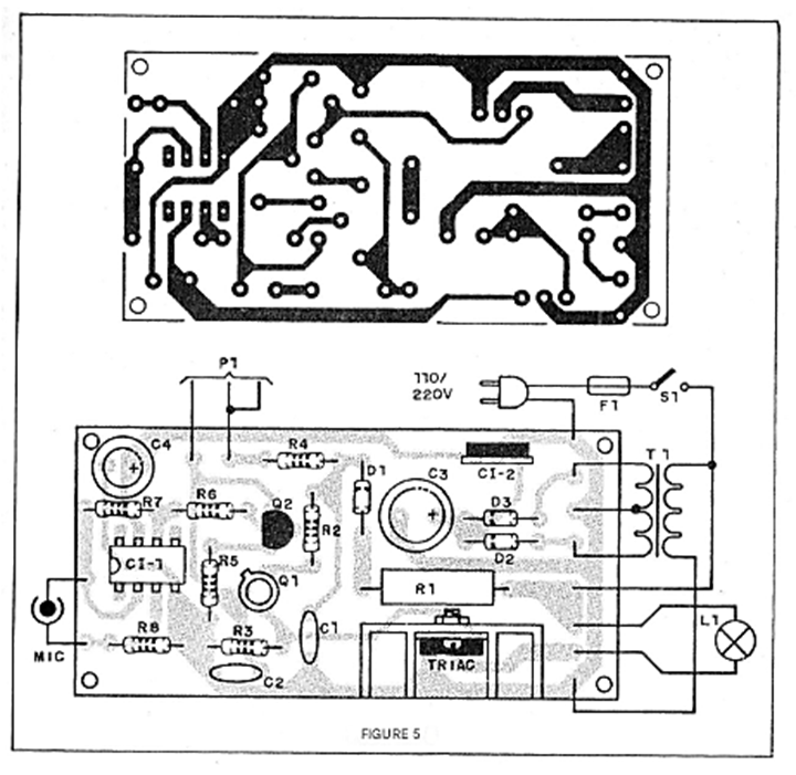
Note the need for wide tracks for the points where the most intense currents pass, i.e., in the triac's load circuit. It will be convenient to use a socket for the integrated circuit. The transformer, which can be placed outside the printed circuit board, does not need to supply more than 200 mA. Small 12 + 12 V transformers can then be used.
The primary winding will depend on your power supply, as will the value of R1. This resistor should be increased to 56kΩ if your power supply is 220V.
The positions of the transistors, diode D1 and other diodes, as well as the integrated circuit, are critical. The reader should also carefully observe the polarity of the electrolytic capacitors. The resistors are all 1/8 or ¼ W except for R1, which is 1 or 2 W, depending on the availability of each assembler.
Capacitors C1 and C2 can be polyester or ceramic, while the others should be electrolytic. The working voltage of C3 should be at least 2.5V. C4 should have a working voltage of at least 16V. For the microphone, there are several possibilities. We especially recommend the use of a telephone capsule or a 200-ohm recorder microphone.
In the absence of these, a small loudspeaker can be used directly, and if the desired sensitivity is not achieved, a transformer connected to the circuit can be used, as shown in Figure 6.
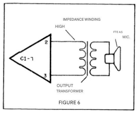
The transformer can be an output transformer for transistors, for vacuum tubes, or, as a last resort, even a power transformer with a 110/220 V primary and a 5 to 12 V secondary with a current of 200 mA to 500 mA. The low-voltage winding side goes to the microphone (loudspeaker). The wire connecting to the microphone does not need to be shielded, but it should not be too long. Do not move the microphone more than 2 meters away from the device's input.
TESTING AND USE
For testing, simply connect a common 25-to-100W light bulb in place of L1, according to your mains voltage. Then, place a fuse at F1 and activate S1. Adjust P1 so that the bulb is at maximum brightness, but at the point where it begins to dim. Clap or speak into the microphone. Your voice should act on the circuit, causing the bulb to flash. Adjust P1 so that the effect has maximum amplitude.
To use, install the microphone so that it can receive ambient sound well.
The total sum of the power of the bulbs should be a maximum of 800 watts on a 110 V mains supply and a maximum of 1600 W on a 220 V mains supply. For operation at the limit, ensure that the triac's heat sink is as large as possible and receives adequate ventilation. In this case, the enclosure must have adequate ventilation, or the triac must be installed externally.
LIST OF MATERIALS
Triac – TlC226 - according to the mains voltage. 200 V for 110 V mains and 400 V for 220 V mains. Use a heat sink.
IC-1 TL071 or CA3140 – integrated circuit - operational amplifier with FE T
Q1 - 2N2646 - unijunction transistor
Q2 - BC548 or equivalent NPN transistor
MIC - dynamic microphone from 4 to 600 ohms - see text
P1 – 100 k – potentiometer
Cl-2 - 7812 - voltage regulator integrated circuit
L1 - 800-or-1600-watt lamps see text
D1, D2, D3 - 1N4004 or 1N4007 rectifier diodes
T1 - Power transformer: primary according to the local mains voltage and secondary of 12 + 12 V from 100 to 500 mA
F 1 - 10 A fuse
R1 – 33 k x 1 W - resistor (orange, orange, orange) or 56k for 220 V mains voltage (green, blue, orange) R2 - 470 ohms - resistor (yellow, violet, brown)
R3 - 330 ohms - resistor (orange, orange, brown)
R4 – 10 kΩ - resistor (brown, black, orange)
R5 – 2.2 kΩ - resistor (red, red, red)
R6 – 100 kΩ - resistor (brown, black, yellow)
R7 - 2.2 MΩ - resistor (red, red, green)
R8 – 100 kΩ - resistor (brown, black, yellow)
C1 - 10 nF - ceramic or polyester capacitor
C2 - 100 nF - ceramic or polyester capacitor
C3 - 1000 uF - electrolytic capacitor (16 V or more)
C4 - 100 uF - electrolytic capacitor (12 V or more)
Miscellaneous: power cable, mounting box, wires, solder, button for P1, heat sink for the triac, support for Fuse, screws, nuts, etc.


