ART3918S ART5533
Note: Article published in Eletrônica Total magazine 153 of 2012.
We inform readers that all circuits have been previously tested, and the results will depend only on the quality of the components used and the skill of the assembler. We have the basic idea of providing simple solutions based on traditional components and that, for this reason, can be developed quickly and easily without the need for special resources.
30-150 MHz Oscillator
With the circuit shown in Figure 1 we can generate signals in the 30 to 150 MHz range, which can be very useful in testing and adjusting receivers, in determining sensitivity to interference in this range by telecommunications equipment, or even in a small data link for the VHF band. Modulation, if necessary, can be done by applying the modulating signal to the base or emitter of the transistor, according to its amplitude.
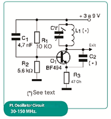
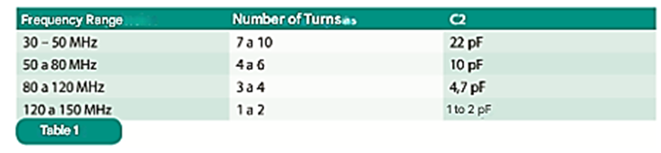
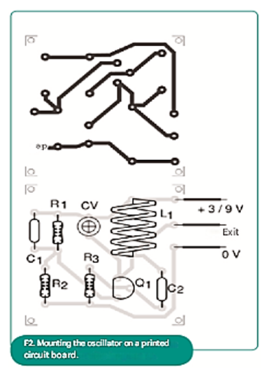
The operating frequency depends on the coil, which can be wound with 18 to 22 AWG enameled wire in a 1 cm diameter coreless form, as shown in Table 1. Note that the value of C2 also depends on the frequency range.
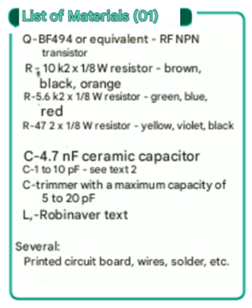
The transistor can be a BF494 or equivalent, and all capacitors should be good quality ceramic. For fine frequency adjustment, the trimmer can have values between 5 and 20 pF of maximum capacitance. Figure 2 shows a suggested printed circuit board layout for assembling this circuit.
Rare PWM H-Bridge
The circuit shown in Figure 3 can control the speed of a motor connected to an H-bridge. This circuit can also be used for direct control of DC motors with maximum currents that depend only on the field-effect transistor used. Currents up to about 10 A can be controlled with motors, not only 12 V, but even with higher voltages.
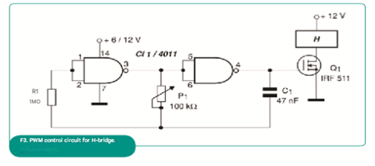
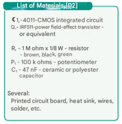
The control range should be obtained experimentally as a function of the value of capacitor C. Depending on the motor, changes in the value of this component may be necessary to avoid motor vibration at very low speeds. The 4011 power supply should be 6 to 12 V with a common ground in relation to the power supply that feeds the motor, which may have different voltages.
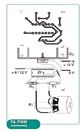
Figure 4 shows a suggested printed circuit board layout for assembling this control. The field-effect transistor can be of any N-channel type and must have a heat sink compatible with the controlled current.
Parallel Interface
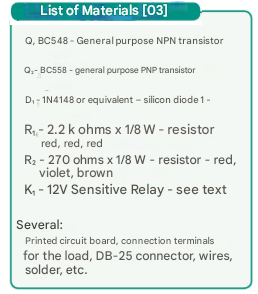
The circuit shown in Figure 5 is a quick solution for controlling an external load via relay using signals obtained from the parallel port of a PC. We can use this circuit as part of a control interface in automated equipment testing using software, or even for testing equipment that needs to be controlled by a computer.
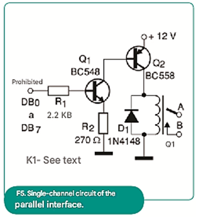
The recommended relay is a sensitive type with a coil current of 50 mA and contact current according to the load to be controlled. The relay voltage depends on the external power supply for this section of the circuit.
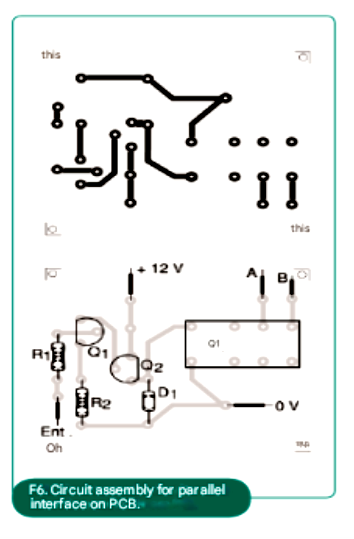
We only show one control channel, but a complete interface can be developed using 8 circuits like this one. Figure 6 shows a suggested printed circuit board layout where the relay used has a DIL package. For other types of relays, the board design must be modified.
The connection to the computer should be made through a DB-25 connector on outputs DBO to DB7, according to the control line that will be used in the application.
Thermocouple Amplifier
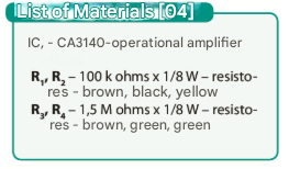
In the absence of a circuit to amplify the signals from a thermocouple in temperature control or other industrial application, the configuration shown in Figure 7 can be an interesting solution.
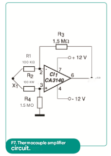
The CA3140 consists of an operational amplifier with junction field-effect transistors (JFETs) at the input, which gives it an extremely high input impedance. The circuit gain is given by the ratio between R3 and R1, with component values that can be changed according to the application.
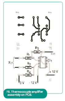
Note that the power supply used does not need to be symmetrical, but it must have excellent filtering given the high gain of the circuit. Figure 8 shows a suggested printed circuit board layout for assembling this application.
We also inform you that equivalent operational amplifiers such as those in the TL070 and TL080 series can be experimented with.
H-Bridge with Power MOSFETs
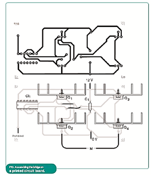
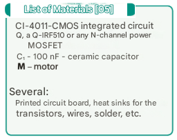
The circuit shown in Figure 9 allows the control of DC motors of various amperes from CMOS logic signals. Two of the gates of a 4011 integrated circuit are used as inverters. They are connected in such a way that when one is at a high output level, the other is necessarily at a low output level.
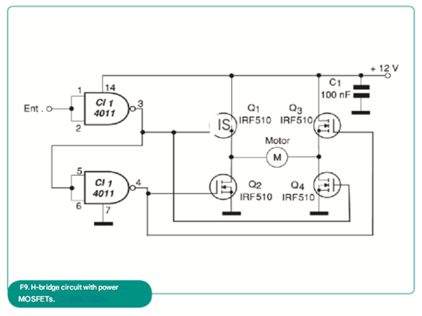
In this way, the power field-effect transistors that form the H-bridge conduct in pairs, establishing different directions of current flow through the motor. With a high level at the input, the motor rotates in one direction, and with a low level, in the opposite direction. The maximum current of the controlled motor depends only on the transistors chosen.
The power supply can be at voltages other than 12 V, depending on the motor used. With voltages below 9 V, the resistance between the drain and source of the transistors begins to become sensitive to losses for the motor.
Eventually, it may be necessary to connect a 1 to 10 pF (non-polarized) capacitor in parallel with the motor to avoid instabilities caused by the commutation of its brushes. Figure 10 shows a suggested printed circuit board layout for this assembly. Note that, depending on the current intensity required by the motor, the transistors must be fitted with appropriate heat sinks.