
ART4001S ART5621
Michael A. Shustov
In practice, it is often necessary to convert signals taken from an external pulse generator into pulse width modulated signals. Figures 1-3 show a series of schemes designed to solve this problem. All these devices are compact accessories for a conventional pulse generator. In particular, as an external pulse generator, a rectangular pulse generator is used, operating at a frequency of 1 kHz with a pulse fill factor of about 50%.
Figure 1 shows an example of using the integrated circuit IC1 CD4050A (voltage repeater) to convert a rectangular input pulse with a 50% fill factor into an adjustable pulse width modulated signal with a fill factor from 0 to 100%.
The input signal from the external pulse generator is fed to the RC circuit R1, C1 and then to the input of the voltage repeater IC1.1. From the output of the voltage repeater through diode D1 and resistor R2, the signal is fed to the repeater input, thus maintaining the voltage across capacitor C1. A circuit consisting of a resistor R3 and a potentiometer P1 is connected in parallel to capacitor C1. Adjusting this potentiometer allows smoothly adjusting the width of the output signals from zero to 100%.
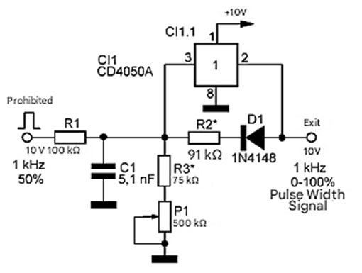
Figure 2 shows a circuit of similar construction; however, discrete elements are used as a voltage repeater, i.e., transistors Q1–Q4, which simulate a CD4050A voltage repeater.
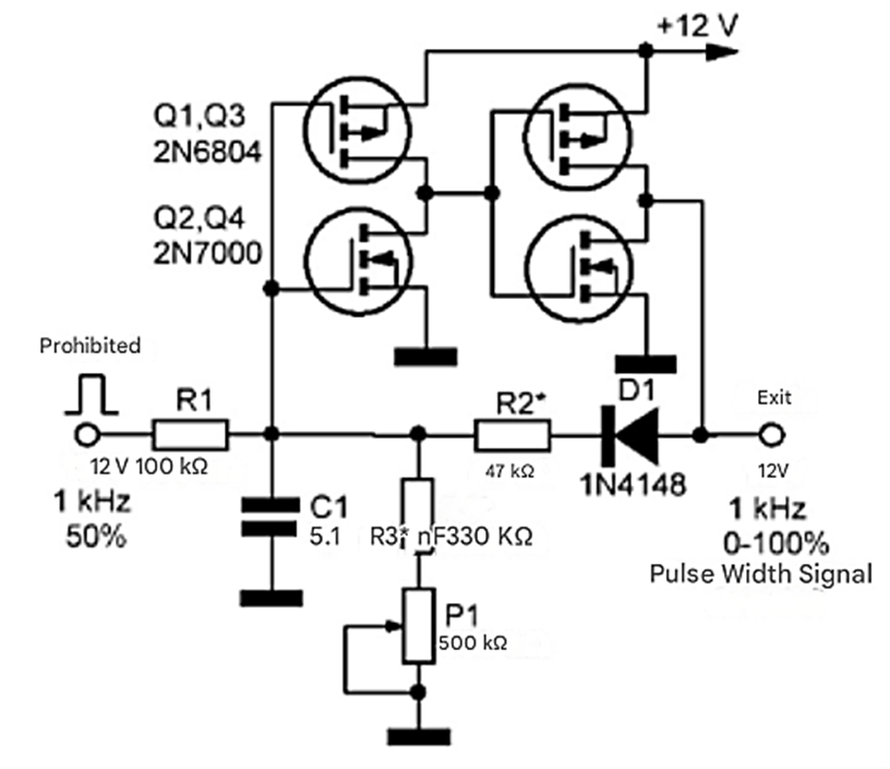
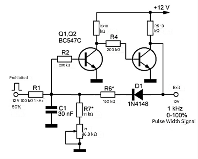
Figure 3 shows another example of a similar device made in bipolar transistors Q1 and Q2.
The amplitude of the input signal must correspond to the supply voltage of the device. When using input generators operating at other frequencies, it will be necessary to select resistive and/or capacitive circuit elements.


